After seeing some posts with EspHome and Zigbee keypads, I realized I wanted to make one too. I wanted the ability to easily trigger more complex actions in home assistant that I don’t have an easy way to fully automate. I decided to make the EspDeck project to provide construction and technical details on building one of these macro pads. EspDeck provides a 9 key macro pad supporting single, double, and hold click actions on every key and can be integrated with home assistant easily through the ESPHome integration or add-on.
Related Articles
- EspDeck Version 1
- EspDeck Version 2
- EspDeck Version 3
- EspDeck Version 3 + LED Backlighting
- EspDeck Automations
- EspDeck + NFC: The NFC Deck
- NfcDeck Backlit Key Notification
Hardware
- 9 x mechanical keyboard switches
- 9 x key caps
- 1 x ESP8266
- 9 x 10k Ohm Resistors
- 1 x Circuit Protoboard
- Some 3d Printing Filament or another material for a case
- Hot Glue (we’re professionals around here)
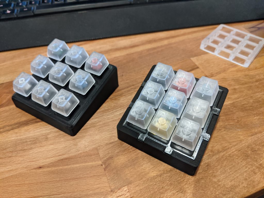
I have been planning on buying a mechanical keyboard for a while now, so I decided to get some key switch sample packs to see which type of key switch I like the most, and then make a few EspDecks, with the samples. This is where I got the set of 9 key switches and caps, though larger packs of key switches are more efficient on price. I will make use of the included key caps until I get around to customizing the key caps for each key function.
I still had the ESP8266 boards from my WLED shenanigans, so all I had to pick up were some resistors and protoboards for that end of things.
Dev Environment
I had never used ESPHome before, so I had to start out by setting up my dev environment. I installed home assistant on a VM, so passing around USB devices can get to be a bit difficult (rebooting the VM to pick up new USB devices passed through). So instead, I decided to pull out an old laptop and install Pop!_OS to use as my base. Installing the OS had one minor snag (the installer failed on some final steps, but the install was fine to run), but still gave me a working physical linux machine. Once it was ready, it was time to start installing what we need.
sudo apt-get install python3 python3-pip
pip install wheels
pip install esphome
Next up I needed to include ESPHome in my PATH variable (and my .bashrc file to keep the setting around after reboot). This will let me call the application without navigating to its binary on the filesystem. This is relatively easy to do and is included at the end of the ESPHome installer as a final manual step.
stephen@pop-os:~$ export PATH=$PATH:$HOME/.local/bin
stephen@pop-os:~$ esphome version
Version: 2022.1.2
stephen@pop-os:~$ nano .bashrc
Since I will be working on USB devices, I needed to update the groups on my user account as well. My user account needed the tty and dialout groups added to it in order to use ESPHome to write the firmware to the ESP devices.
stephen@pop-os:~$ groups
stephen adm sudo lpadmin
stephen@pop-os:~$ compgen -g
root
daemon
bin
sys
adm
tty
disk
lp
mail
news
uucp
man
proxy
kmem
dialout
.............
stephen
systemd-coredump
stephen@pop-os:~$ sudo usermod -a -G tty stephen
stephen@pop-os:~$ sudo usermod -a -G dialout stephen
With my user account in the tty and dialout groups, I’ll now be able to run ESPHome and write my firmware to the ESP8266 devices. In order for this to fully take effect, you need to log out and log back into the system.
Time to take care of the first run wizard with ESPHome. In this wizard, we give it our Wi-Fi SSID, password, board details, and other information.
stephen@pop-os:~$ esphome
usage: esphome [-h] [-v] [-q] [-s key value] command ...
esphome: error: the following arguments are required: command
stephen@pop-os:~$ esphome wizard keypad.yaml
Hi there!
I'm the wizard of ESPHome :)
And I'm here to help you get started with ESPHome.
In 4 steps I'm going to guide you through creating a basic configuration file for your custom ESP8266/ESP32 firmware. Yay!


============= STEP 1 =============
    _____ ____  _____  ______
   / ____/ __ \|  __ \|  ____|
  | |   | |  | | |__) | |__
  | |   | |  | |  _  /|  __|
  | |___| |__| | | \ \| |____
   \_____\____/|_|  \_\______|

===================================
First up, please choose a name for your node.
It should be a unique name that can be used to identify the device later.
For example, I like calling the node in my living room livingroom.

(name): keypad1
Great! Your node is now called "keypad1".


============= STEP 2 =============
      ______  _____ _____
     |  ____|/ ____|  __ \\
     | |__  | (___ | |__) |
     |  __|  \___ \|  ___/
     | |____ ____) | |
     |______|_____/|_|

===================================
Now I'd like to know what microcontroller you're using so that I can compile firmwares for it.
Are you using an ESP32 or ESP8266 platform? (Choose ESP8266 for Sonoff devices)

Please enter either ESP32 or ESP8266.
(ESP32/ESP8266): ESP8266
Thanks! You've chosen ESP8266 as your platform.

Next, I need to know what board you're using.
Please go to http://docs.platformio.org/en/latest/platforms/espressif8266.html#boards and choose a board.

For example "nodemcuv2".
Options: d1, d1_mini, d1_mini_lite, d1_mini_pro, esp01, esp01_1m, esp07, esp12e, esp210, esp8285, esp_wroom_02, espduino, espectro, espino, espinotee, espmxdevkit, espresso_lite_v1, espresso_lite_v2, gen4iod, heltec_wifi_kit_8, huzzah, inventone, modwifi, nodemcu, nodemcuv2, oak, phoenix_v1, phoenix_v2, sonoff_basic, sonoff_s20, sonoff_sv, sonoff_th, sparkfunBlynk, thing, thingdev, wifi_slot, wifiduino, wifinfo, wio_link, wio_node, xinabox_cw01
(board): esp12e
Way to go! You've chosen esp12e as your board.


============= STEP 3 =============
   __          ___ ______ _
   \ \        / (_)  ____(_)
    \ \  /\  / / _| |__   _
     \ \/  \/ / | |  __| | |
      \  /\  /  | | |    | |
       \/  \/   |_|_|    |_|

===================================
In this step, I'm going to create the configuration for WiFi.

First, what's the SSID (the name) of the WiFi network keypad1 should connect to?
For example "Abraham Linksys".
(ssid): my-wifi-ssid
Thank you very much! You've just chosen "my-wifi-ssid" as your SSID.

Now please state the password of the WiFi network so that I can connect to it (Leave empty for no password)

For example "PASSWORD42"
(PSK): **************
Perfect! WiFi is now set up (you can create static IPs and so on later).


============= STEP 4 =============
       ____ _______
      / __ \__   __|/\\
     | |  | | | |  /  \\
     | |  | | | | / /\ \\
     | |__| | | |/ ____ \\
      \____/  |_/_/    \_\\

===================================
Almost there! ESPHome can automatically upload custom firmwares over WiFi (over the air) and integrates into Home Assistant with a native API.
This can be insecure if you do not trust the WiFi network. Do you want to set a password for connecting to this ESP?

Press ENTER for no password
(password):

DONE! I've now written a new configuration file to keypad.yaml

Next steps:
  > Follow the rest of the getting started guide:
  > https://esphome.io/guides/getting_started_command_line.html#adding-some-features
  > to learn how to customize ESPHome and install it to your device.
Once we have a yaml file ready to test, its one simple command to upload it to the ESP8266 and run it.
stephen@pop-os:~$ esphome run keypad.yaml
Wiring
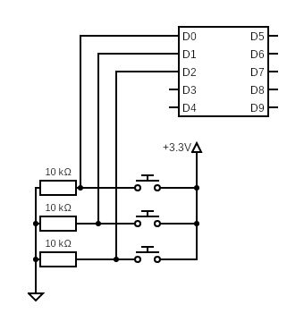
To start out with, we need the pinout of the ESP8266 device thats being used. There are 9 digital input/output pins on the device, which lines up exactly with our 9 keys (it lets us avoid a more complex row/column input layout). I originally tried just configuring ESPHome with D0 as the pin number, this didn’t work, nor did GPIO0, since the GPIO pin numbers do not line up with any of the other pin type numbers on the board. I ended up using this pinout (and shown below).

The circuit design is simple, each digital IO pin has a pull down resistor to ground, as well as a connection to the key switches. The other side of the switch goes to the 3.3V rail of the ESP8266. This gives the digital IO pins a base input of 0 when the switches are open, and an input of 1 when the switches are pressed.
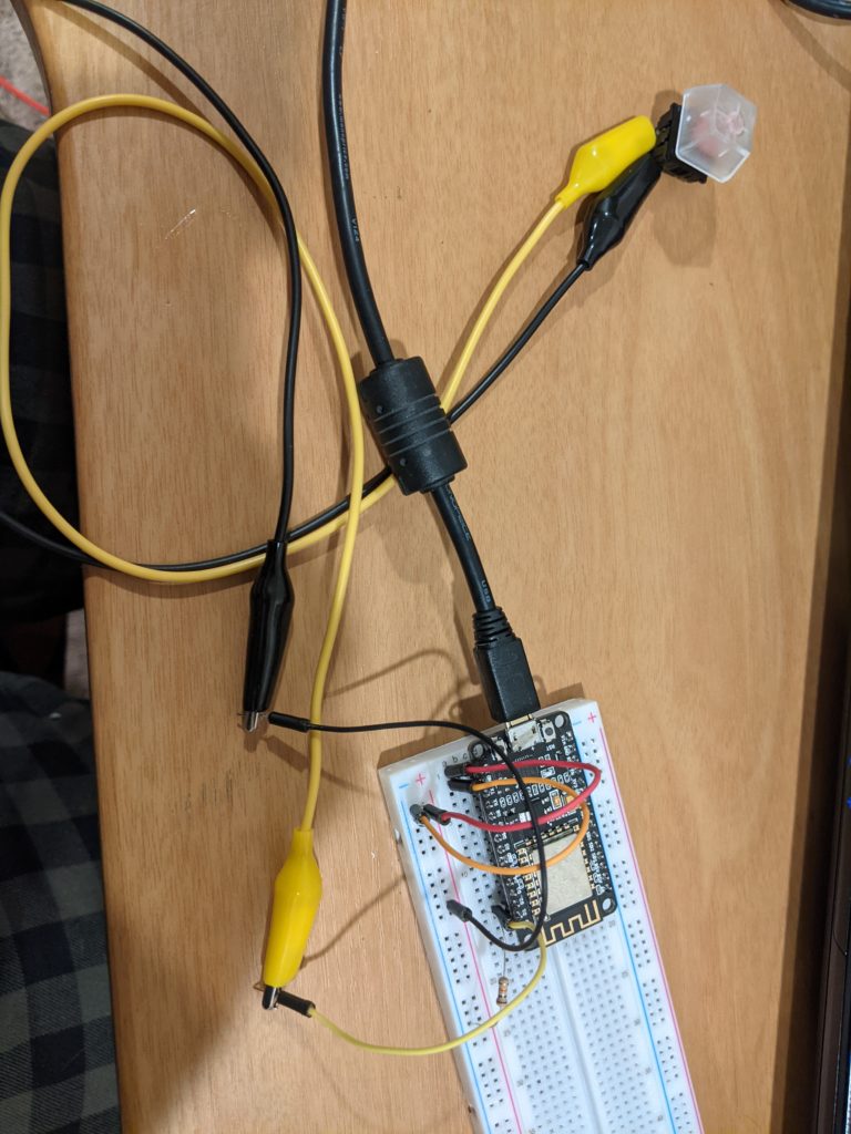
I decided to use a breadboard to prototype out one key on the macro pad as an input into the ESP8266. I used this prototype to develop the configuration for ESPHome to handle the single/double/hold key presses and to route them to Home Assistant
ESPHome Integration
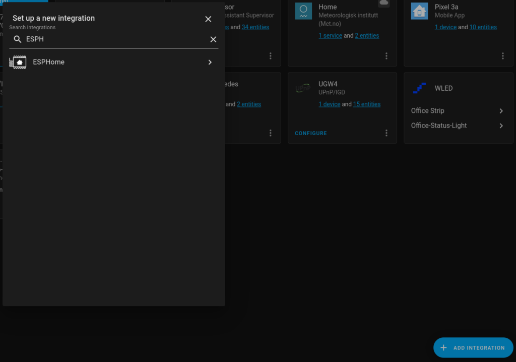
Since I was handling my ESPHome development on a separate machine from Home Assitant (and the remote device support from ESPHome doesn’t support FireFox), I had to add my device to the ESPHome integration manually. I plan on trying the ESPHome Add-On later on, as well as adding my current keypad to the Add-On so I can use it for firmware updates. Until then, the process of manually adding ESPHome is simple in the integrations tab. It can be found in the list by searching for ESP and only needs one bit of information to add a device.
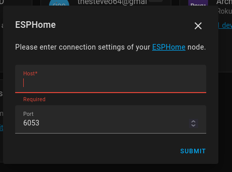
Once ESPHome is added to the integrations, a new device can be added to it. The integration just needs the Host/IP and the port. Since I didn’t manually change the ports in use on my device, I left it on the default.
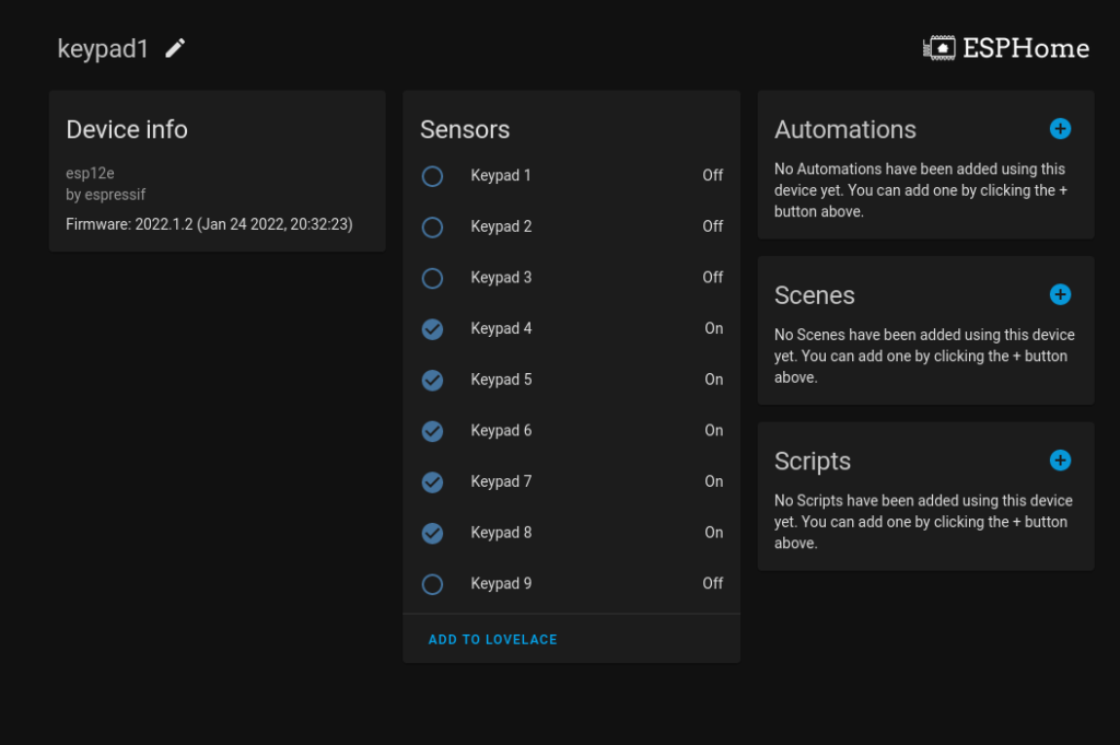
Now with the device configured, the keypad sensors can be seen in their first iteration. I don’t yet have setup the double and click and hold actions. I also don’t have all the pull down resistors in place, so multiple keypad keys are showing as perpetually “ON”.
Developing the Configuration
I started out the configuration by simply getting things going with the GPIO pins marked out for each key. This was enough to be able to get the switches acting on the breadboard and continue working towards the full final configuration.
esphome:
  name: keypad1

esp8266:
  board: esp12e

# Enable logging
logger:

# Enable Home Assistant API
api:
  password: ""

ota:
  password: ""

wifi:
  ssid: "myreallygoodssid"
  password: "myreallygoodpassword"

  # Enable fallback hotspot (captive portal) in case wifi connection fails
  ap:
    ssid: "Keypad1 Fallback Hotspot"
    password: "somethingcomplex"

captive_portal:

binary_sensor:
  - platform: gpio
    name: "Keypad 1"
    pin: 16
  - platform: gpio
    name: "Keypad 2"
    pin: 5
  - platform: gpio
    name: "Keypad 3"
    pin: 4
  - platform: gpio
    name: "Keypad 4"
    pin: 0
  - platform: gpio
    name: "Keypad 5"
    pin: 2
  - platform: gpio
    name: "Keypad 6"
    pin: 14
  - platform: gpio
    name: "Keypad 7"
    pin: 12
  - platform: gpio
    name: "Keypad 8"
    pin: 13
  - platform: gpio
    name: "Keypad 9"
    pin: 15
Once I had that basic input working, I went to work on the more complex actions, starting with the click and hold. I realized I needed to create some type of mockup sensor for the held state and the double click states since having just the basic button press sensor wasn’t enough. I used the template sensors as I couldn’t find another way to configure them without hardware attached, and they worked well.
  - platform: template
    name: "Keypad 2 Held"
    id: key_2_held_state
  - platform: template
    name: "Keypad 2 Double Click"
    id: key_2_double_click_state
  - platform: template
    name: "Keypad 2 Click"
    id: key_2_click_state
Now that I have my template sensors, I can turn them on and off with lambdas to emulate clicking the button. I’ll start with the click and hold action, with the goal to require the button to be held for at least 1 second, then it turns on the key_2_held_state for 1 second before turning it off. You can also see some of my experimenting with the home assistant service and the binary sensor toggle. I realized the home assistant service wasn’t going to work the way I expected and removed it later on.
    on_click:
        min_length: 1s
        then:
          - logger.log: "Key 2 Held"
          - homeassistant.service:
              service: input_boolean.turn_on
              data:
                entity_id: input_boolean.Keypad_2_held
          - binary_sensor.toggle: key_2_held_state
          - delay: 1s
          - binary_sensor.toggle: key_2_held_state
          - lambda: !lambda |-
              id(key_2_held_state).publish_state(true);
This didn’t quite work as expected since the binary_sensor toggle action didn’t work out. Instead I moved to all lambdas.
    on_multi_click:
      - timing:
        - ON for at least 1s
        then:
          - logger.log: "Key 2 MultiHeld"
          - lambda: !lambda |-
              id(key_2_held_state).publish_state(true);
          - delay: 1s
          - lambda: !lambda |-
              id(key_2_held_state).publish_state(false);
Once I had the right formula of lambdas and template sensors, I added in the double click and single click actions. I had finally reached the final key configuration. Each key has 3 states, held, click, and double click. I split out the click state from the raw sensor data to avoid reading the other states also as a single click.
  - platform: template
    name: "Keypad 2 Held"
    id: key_2_held_state
  - platform: template
    name: "Keypad 2 Double Click"
    id: key_2_double_click_state
  - platform: template
    name: "Keypad 2 Click"
    id: key_2_click_state
  - platform: gpio
    name: "Keypad 2"
    pin: 5
    on_multi_click:
      - timing:
        - ON for at most 950ms
        - OFF for at least 500ms
        then:
          - lambda: !lambda |-
              id(key_2_click_state).publish_state(true);
          - delay: 500ms
          - lambda: !lambda |-
              id(key_2_click_state).publish_state(false);
      - timing:
        - ON for at least 1s
        then:
          - logger.log: "Key 2 MultiHeld"
          - lambda: !lambda |-
              id(key_2_held_state).publish_state(true);
          - delay: 1s
          - lambda: !lambda |-
              id(key_2_held_state).publish_state(false);
    on_double_click:
      min_length: 25ms
      max_length: 350ms
      then:
        - logger.log: "Key 2 Double Click"
        - lambda: !lambda |-
              id(key_2_double_click_state).publish_state(true);
        - delay: 1s
        - lambda: !lambda |-
              id(key_2_double_click_state).publish_state(false);
Now just duplicate that configuration 9 times (I’m no professional yaml creator, there is most certainly a better way to do this with less duplication) for the 9 keys.
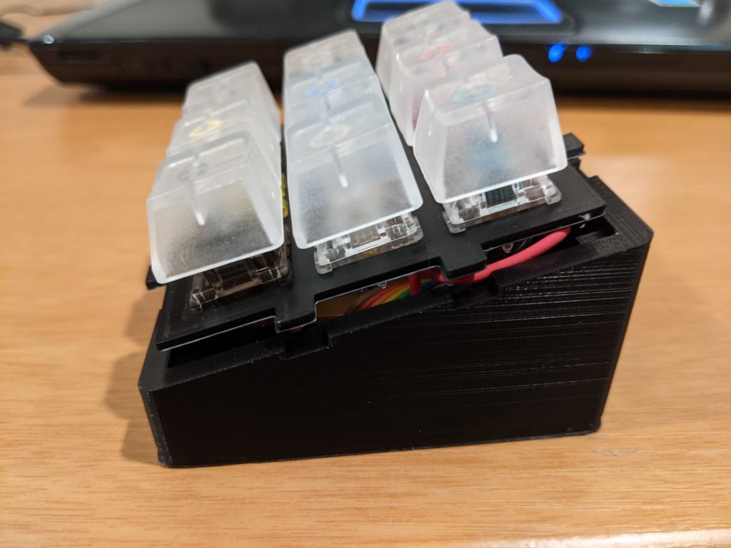
The Case
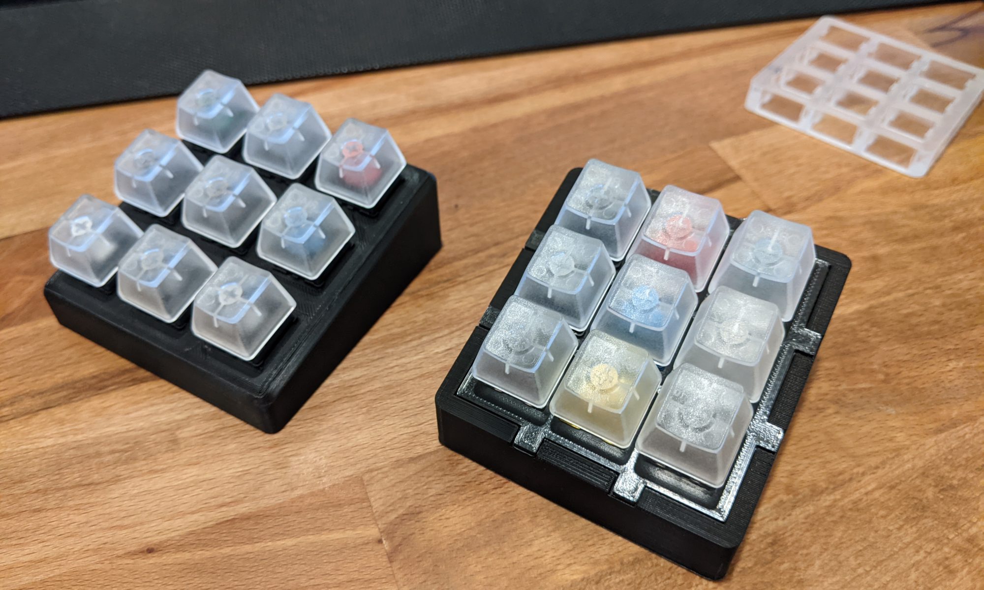
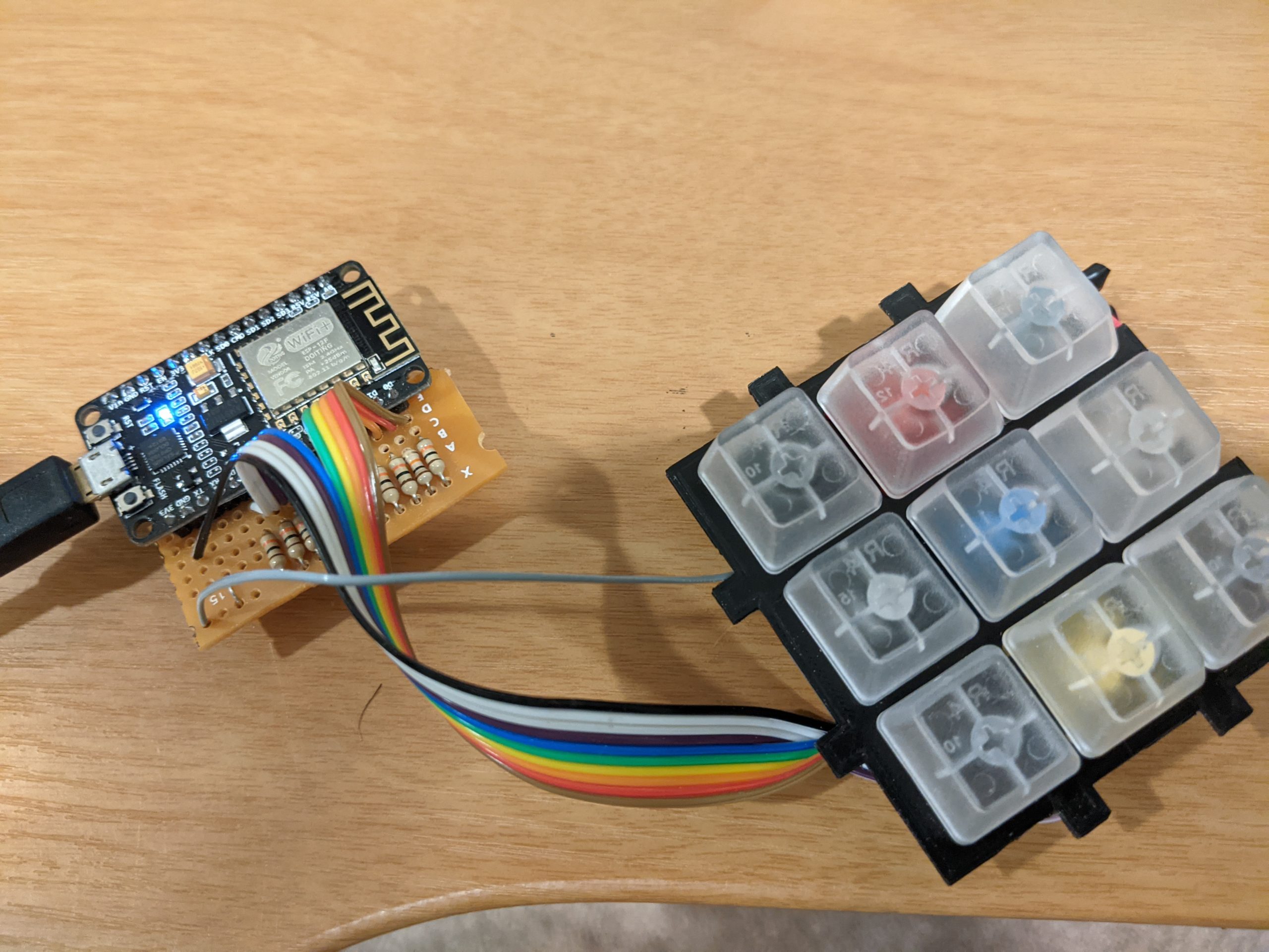
I found two 9-key cases on Thingiverse to try out. I printed out one of each and inserted the key switches I had available. I ended up going with the denser design for the top of the unit.
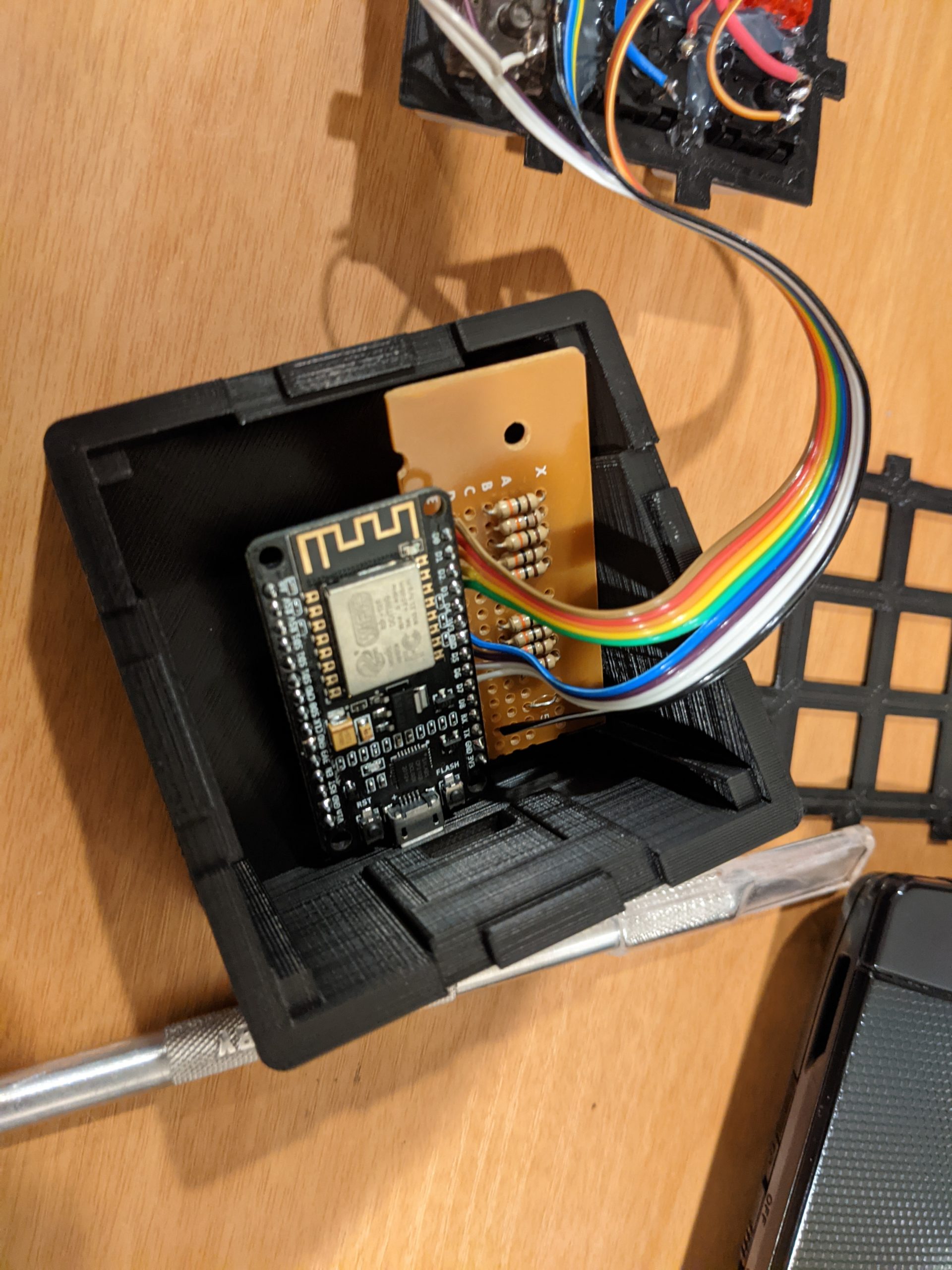
After getting far into the assembly of the unit, I did discover that the original case from Thingiverse was too shallow for my skill of electronics. I made a new version of the case that is deeper to avoid the problem, while a 3rd iteration of the case will be needed eventually.
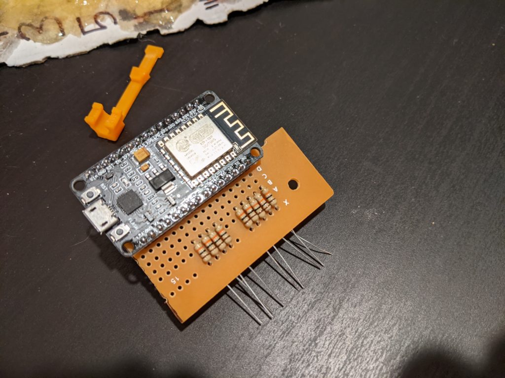
Assembly
I started assembly with the ESP8266 and the protoboard. I wanted to get the pull down resistors wired up first, followed by the cable that will attach all the keys to the ESP device.
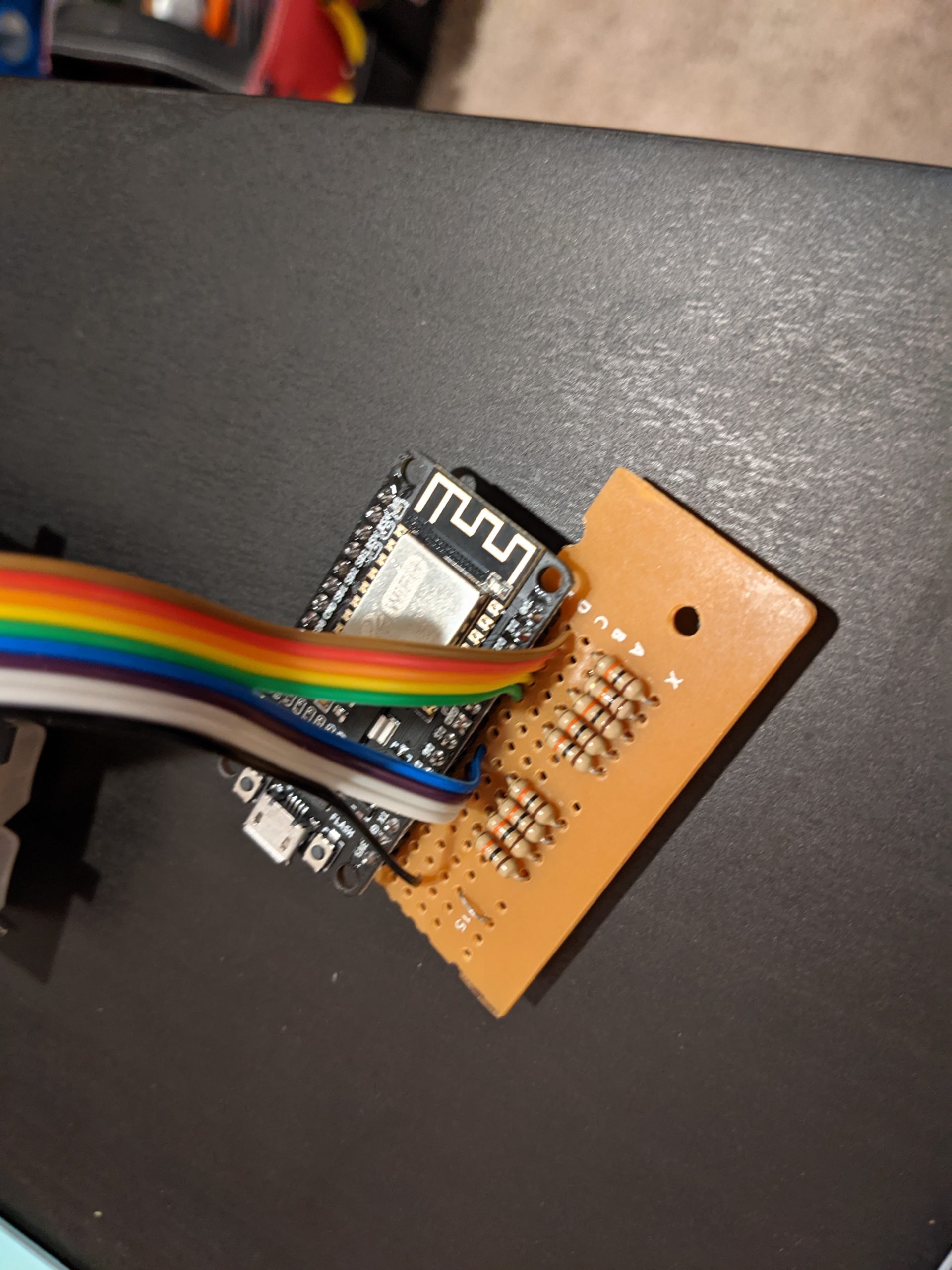
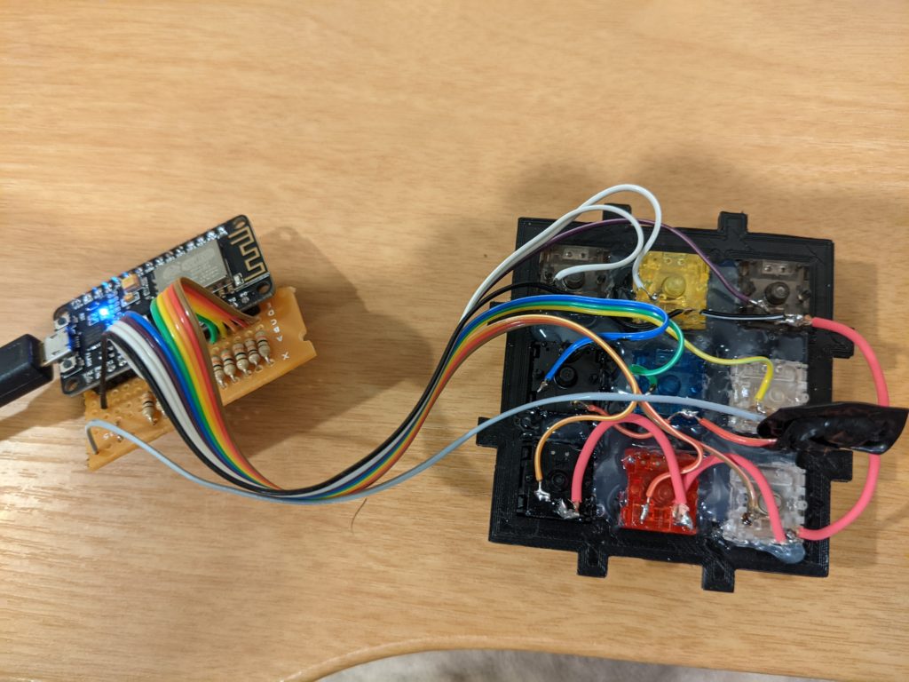
With the protoboard wired up and ready, we go over to the key side of the equation. We hot glue the key switches into the top plate and start wiring them up.
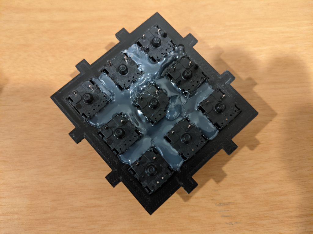
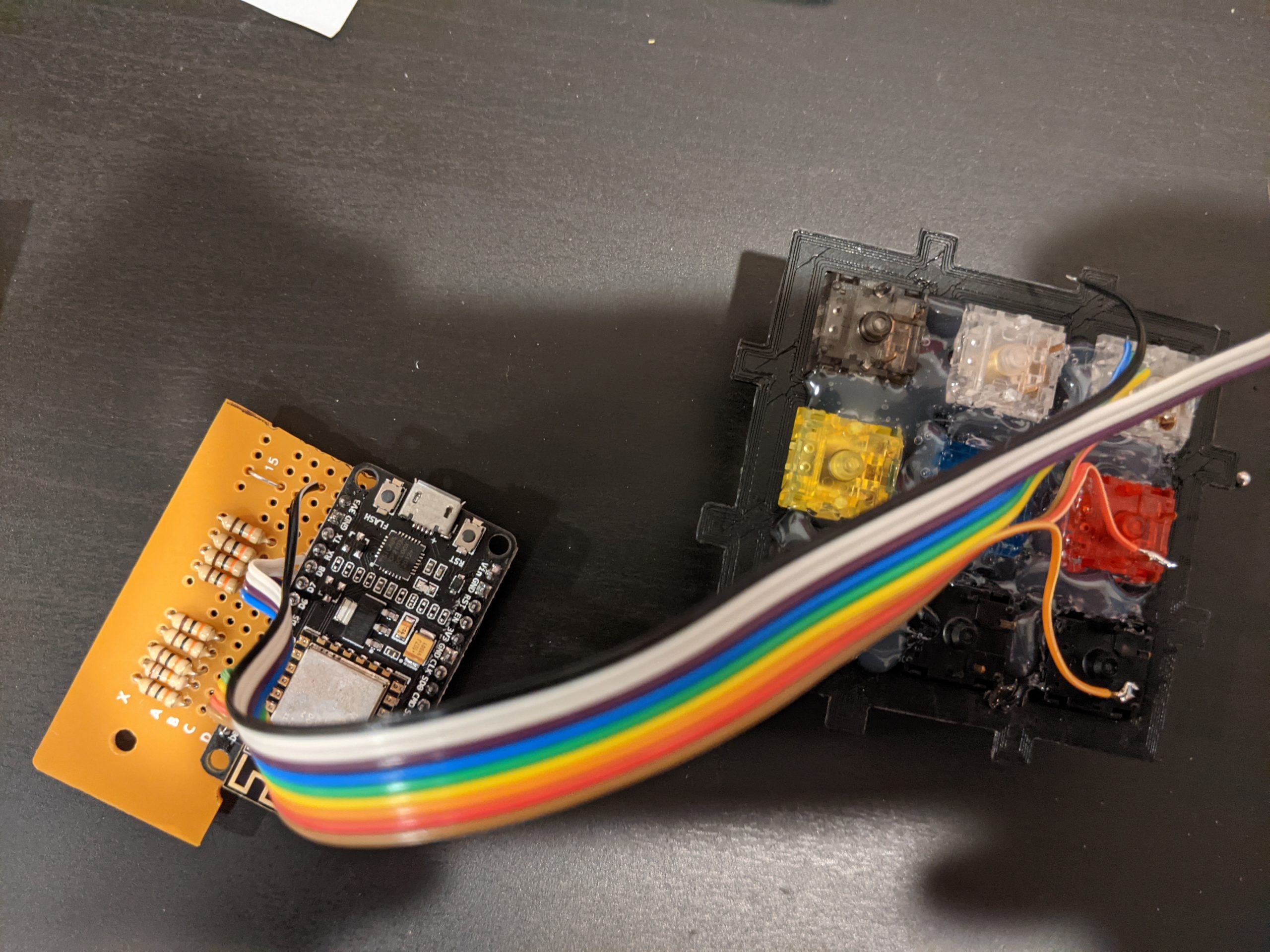
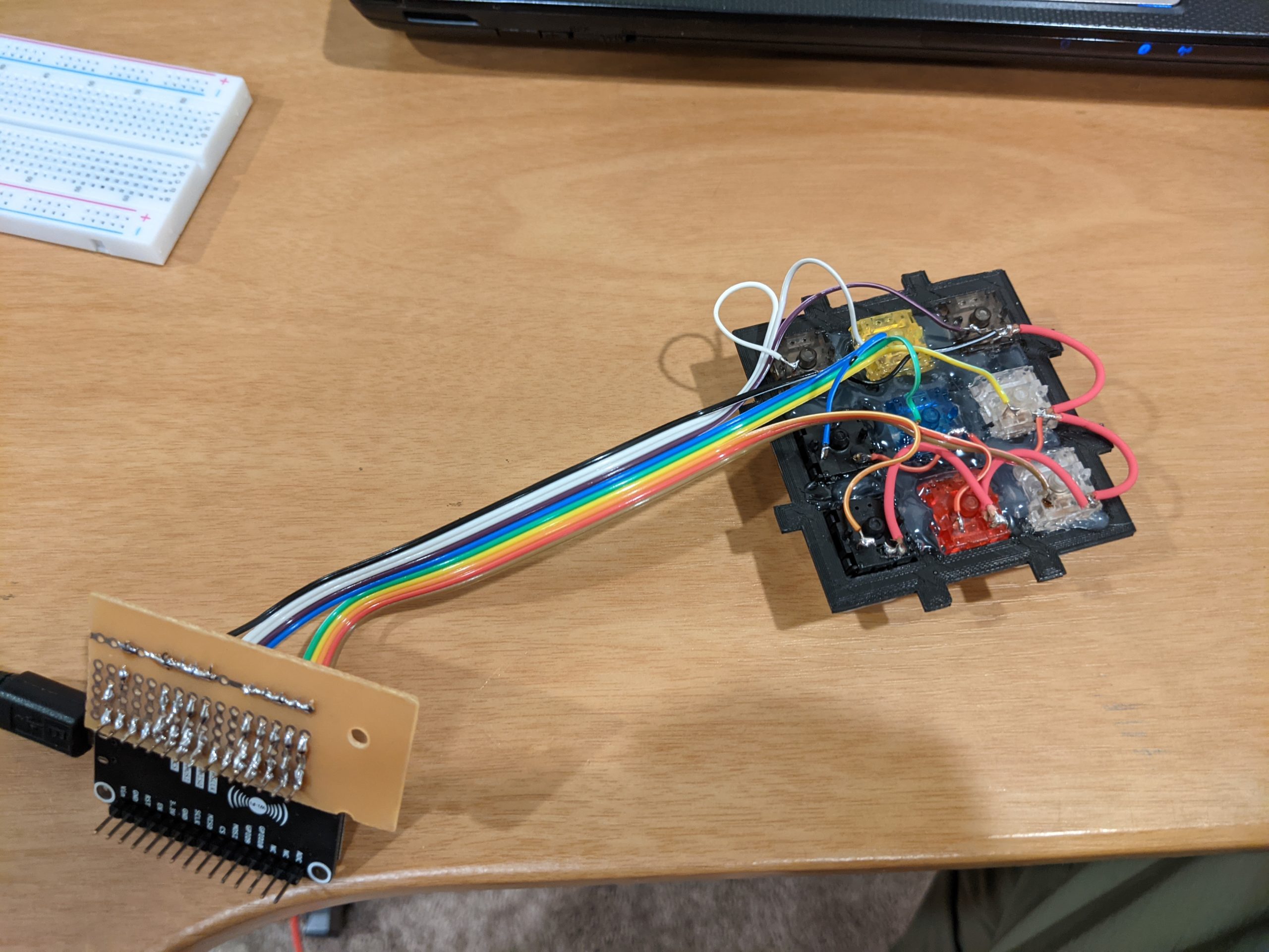
Once everything is all wired up, I ran a few multi-meter checks to make sure that I didn’t short anything out, and followed that up with a quick power on and test. With that test, I found out that I had a problem…. key 4 was broken, it was stuck in a high state even with the pull down resistor.
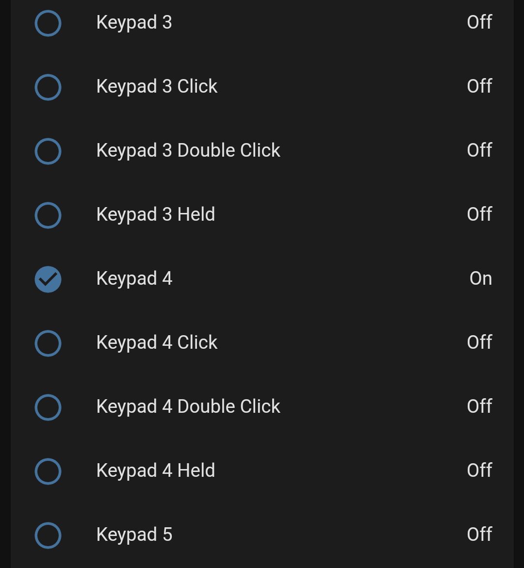
So after some research, I found out that GPIO0 / Key 4 needs to be pulled down by the switch, rather than my current design of having the switches pull up the digital IO pins. This swap can be easily done for just key 4 on this first iteration, however moving all keys to this method would reduce the complexity of my circuit in general and make for a better design. I started by making the electrical changes first and checkout out the switch in home assistant to make sure it was working as expected.
Now that its working, I adjusted the YAML for key #4. Key 4 is now set with the internal pull up enabled explicitly as well as inverting the output of the switch, without the invert, the default position would be “ON” and pressing the key would be registered as an “OFF” state which is opposite how I want the keys to be seen in home assistant.
  - platform: gpio
    name: "Keypad 4"
    pin:
      number: 0
      mode:
        input: true
        pulldown: false
        pullup: true
      inverted: true
    on_multi_click:
..........................
With this final YAML update, I have the configuration done to the EspDeck Gen1. I have all keys working, all actions mapped correctly, and a fully functioning pad. The full/final YAML file can be found in the GitHub repo for the EspDeck (the blog format doesn’t make for the best for hundreds of lines of config file).
Don’t Look Behind the Prototype 1 Curtains
The first generation (sounds much better than first prototype) of the EspDeck has its fair share of problems, and a few solutions. Though in general I plan on solving more of the design problems with the second generation / prototype.
Problems Solved in the First Iteration
- Case was too shallow
- Electrical design failed to account for GPIO0 / Key 4
Problems to Solve for Generation 2
- Electrical design is inefficient (there are ways to avoid using any resistors in the design)
- Electrical design is different for Key 4 / GPIO0 vs the rest of the keys
- The case doesn’t support the esp device
- Hot glue holding the case together
Gen 2 Plans
For generation 2 of the design, I plan on swapping it to use the internal pull ups in the ESP8266, and have the key switches go to ground instead of the +3.3v rail. This should simplify things, removing the need for the resistors, as well as removing the GPIO0 / Key 4 problem.
Another plan is to get a better case design to support the ESP8266 inside the case. Currently its floating in the case and partially hot glued into place along with the USB cable. This needs to get redesigned to make it a bit cleaner and more robust, not needing to hot glue the cable into the case for fear of breaking the USB port would be great. Another addition could be a way to hold the key switch panel on top of the case without hot glue or pressure fitting it. I’m still not sure the best way to handle this, maybe some screws passing through the entire case to thread a few rounds into the top.
Conclusions
I’m happy with the outcome of the first EspDeck I built, though I’m also glad I didn’t build the second EspDeck at the same time. I do have some work on the second pad done that I will want to undo / correct to match my goals for generation 2. I have a few automations already put together on the macro pad, things that would normally take a few actions in the home assistant GUI to do are now one key press away. I just need to keep adding to it, looking for the best points to make things easier to use and to match my uses.
EspDeck Resources
Resources
- EspDeck on GitHub
- EspDeck on Thingiverse
- EspDeck on YouMagine
- RandomNerdTutorials Pinout Guides
- EspHome
Some of the links in this post are affiliate links, which means I may earn a small commission if you make a purchase through them—at no extra cost to you. This helps support the blog and allows me to continue creating content that you love. I will only recommend products and services that I trust and believe will be beneficial to my readers. Thank you for your support!