When I started into the EspDeck project, I had enough parts on hand to build two units. I had two sampler packs of switches and two ESP8266 boards to use. So once I had the gen1 unit built, I started working on generation 2 of the EspDeck. Gen2 has a well designed case that holds the board in place, allows easier plugging in of USB, and a cleaner wiring design.
Related Articles
Hardware
The hardware need to assemble the EspDeck is similar to earlier. It requires far fewer resistors from earlier, and this time around has customizable keycaps.
- ESP-8266
- 9 x Mechanical key switches
- 9 x Relegendable key caps or water slide decal paper
- 1 x 10k Resistor
- Hot glue
- 3d printer filament
- Wire
Upgrades from Generation 1
- Better case design
- Supports the ESP board
- Allows for easier plugging in of USB cables
- Simpler wiring design
- No proto board
- Only one resistor
- Relegendable key caps
Wiring
Using input pullup to avoid needing resistors in the design. This simplifies the wiring and makes assembly take less time. The two oddball inputs (GPIO15 and GPIO16) are covered later as to why they need special treatment, but I made sure my main wiring diagrams here were the final diagrams.
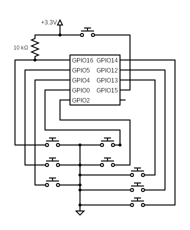
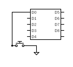
Since the circuit is so simple, we can just simplify the diagram for easy viewing, each switch being the same as the next. This of course is for all switches but GPIO15 and GPIO16.
Case
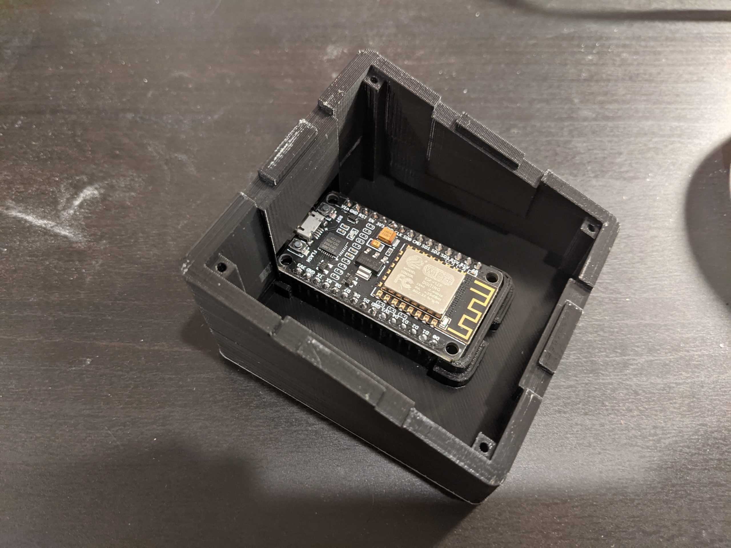
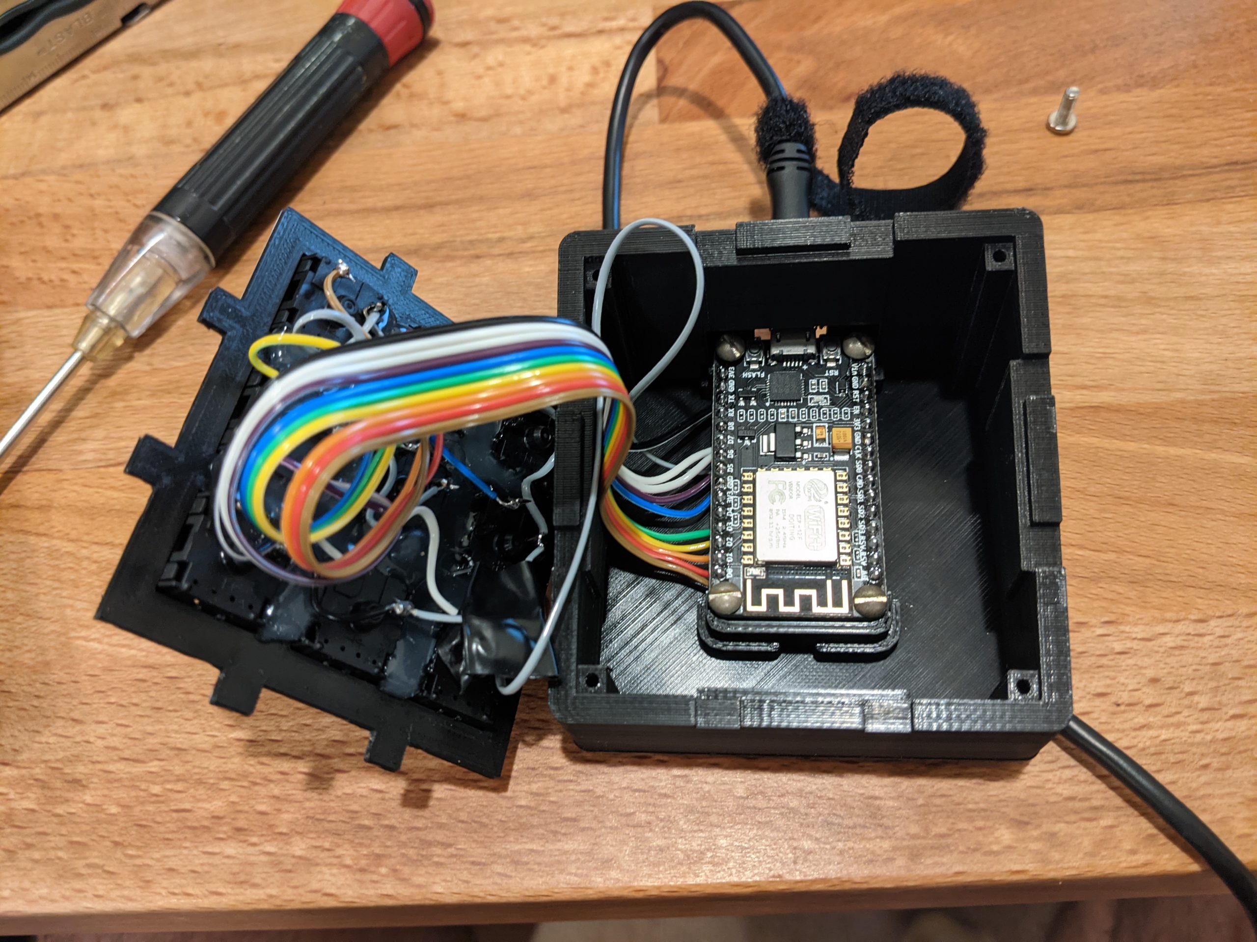
The main drawback of the first case was that it didn’t support the ESP8266 at all in the case, the controller was just free floating. The new case fixes that by having screw mount points for the control board and better support to hold onto it. It also positions the board better for the USB port to be utilized (I hot glued in the cable on gen1 to avoid the free floating board plug in problem).
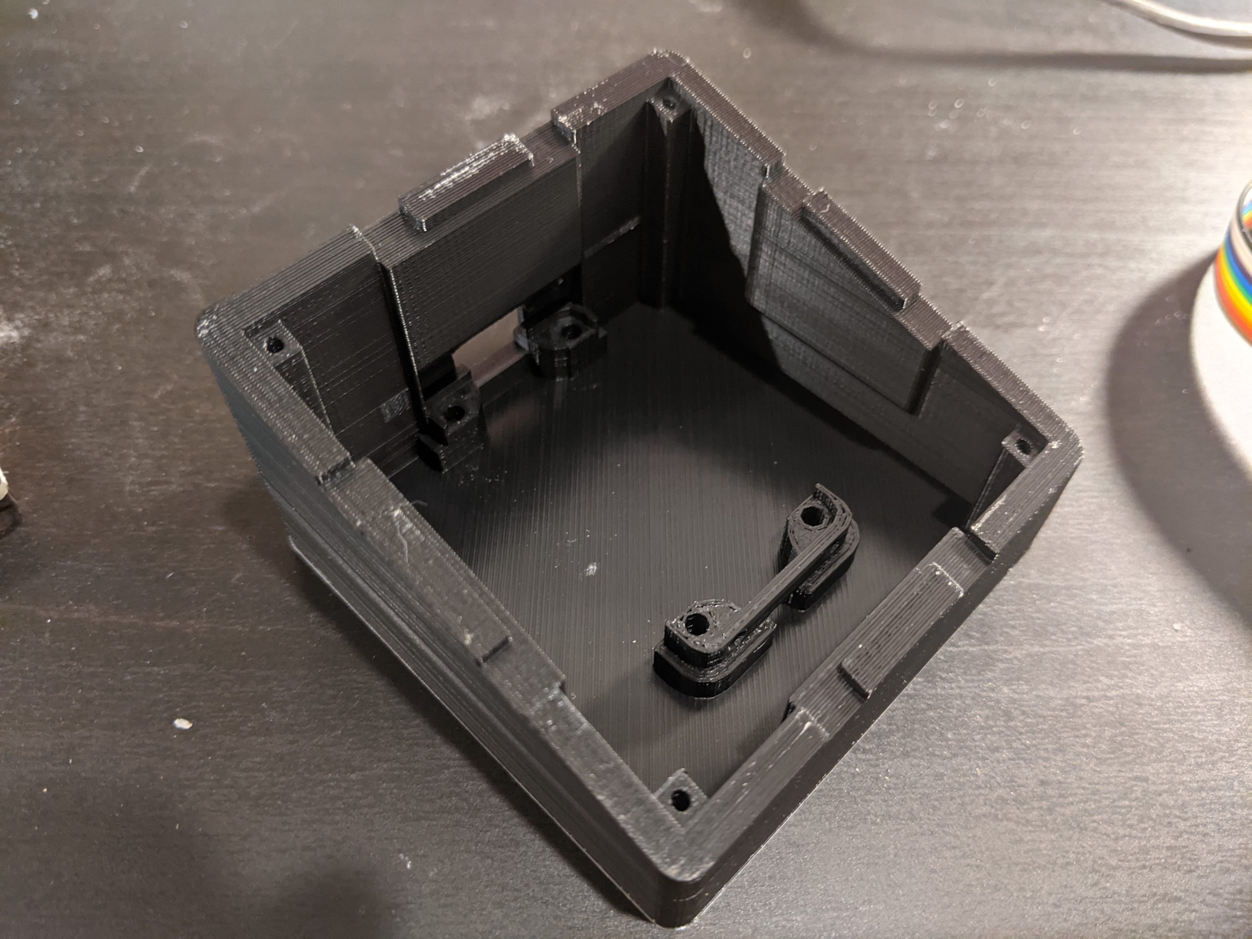
The new case design holds the ESP in place and supports bolting it in place. This will make it easier to plug and unplug unlike gen1 (which might be hot glued in place).
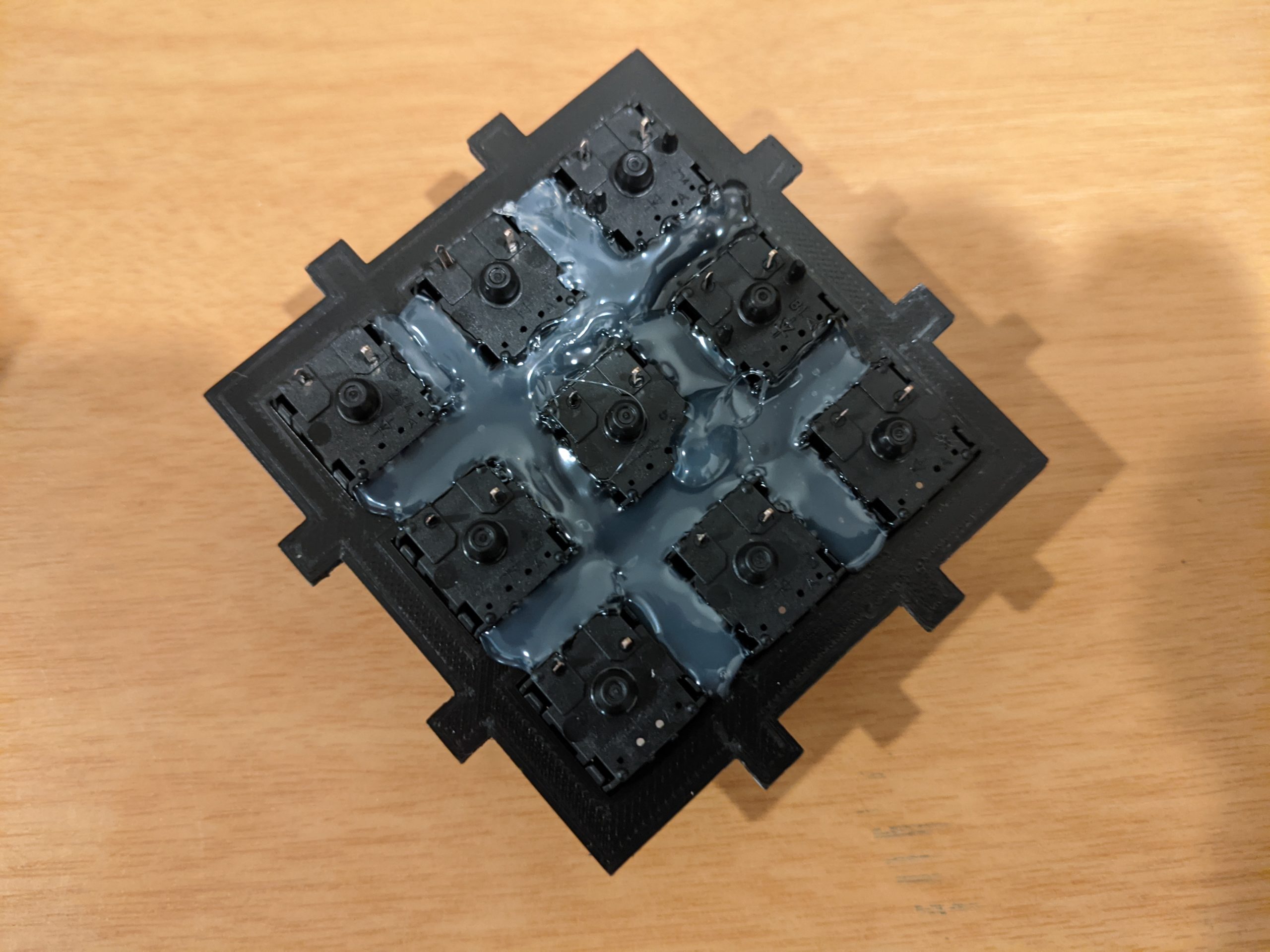
Assembly
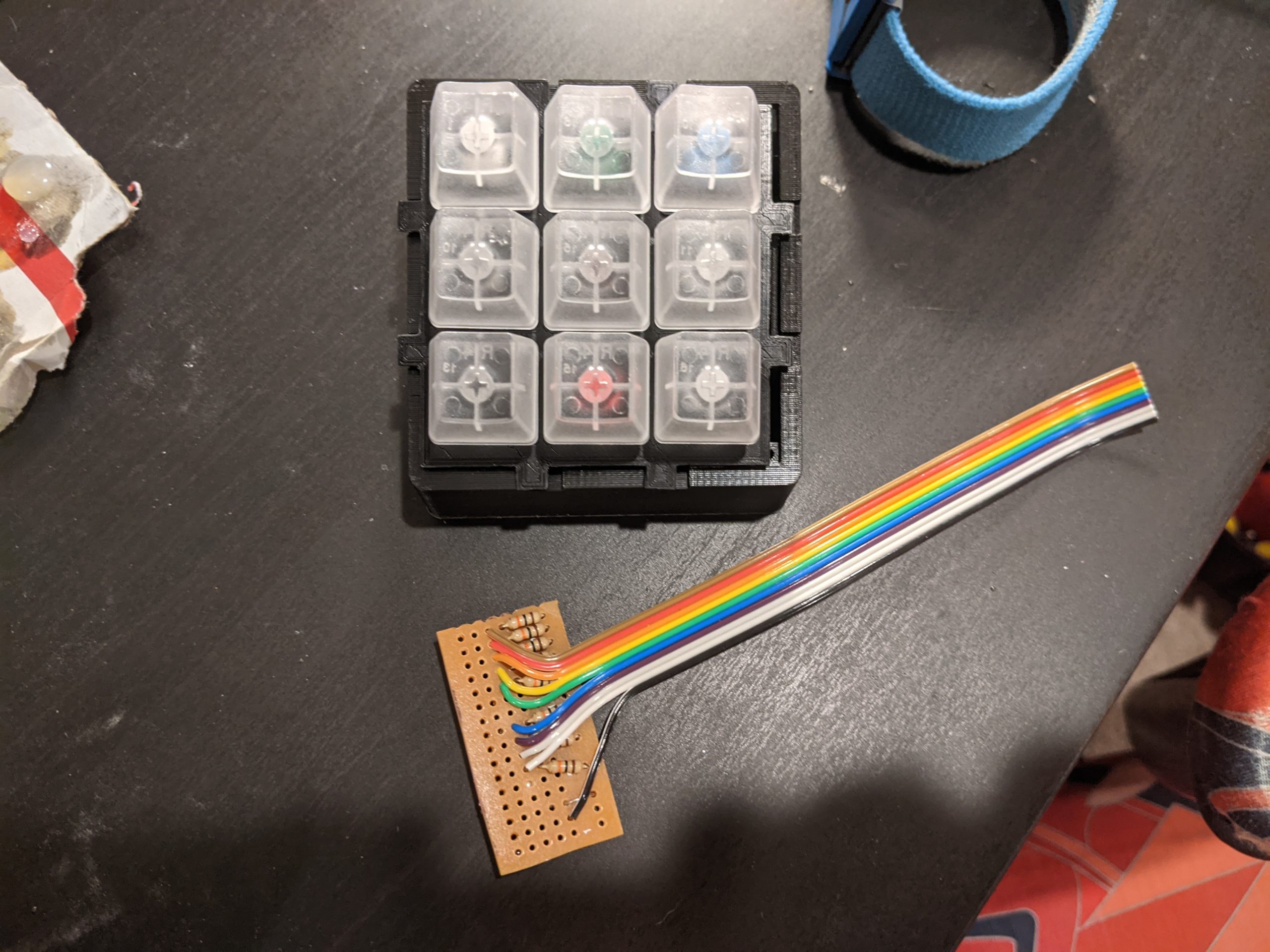
The assembly process is very similar to the generation 1 deck. To start out with, we go to the key switches and the top plate, hot gluing them into place.
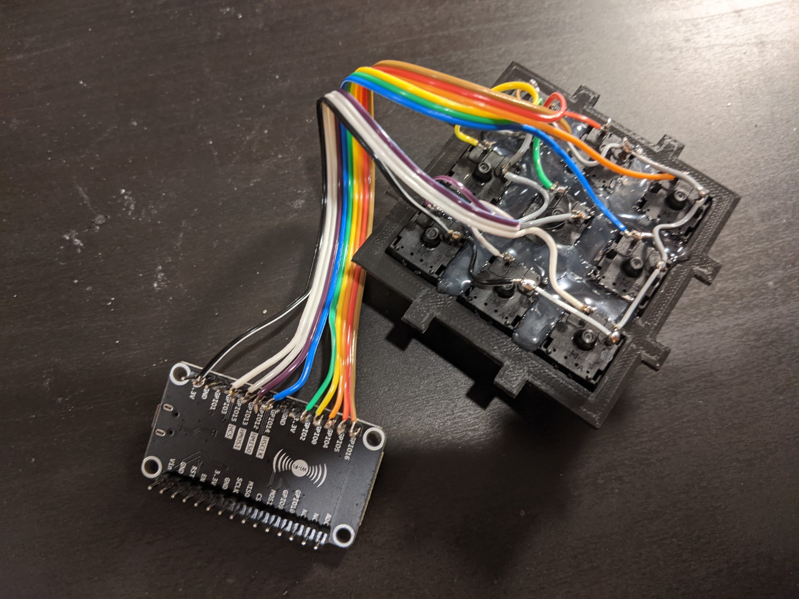
Next up, wiring up all the keys to the ESP. This step is far quicker now that the protoboard and resistors aren’t need.
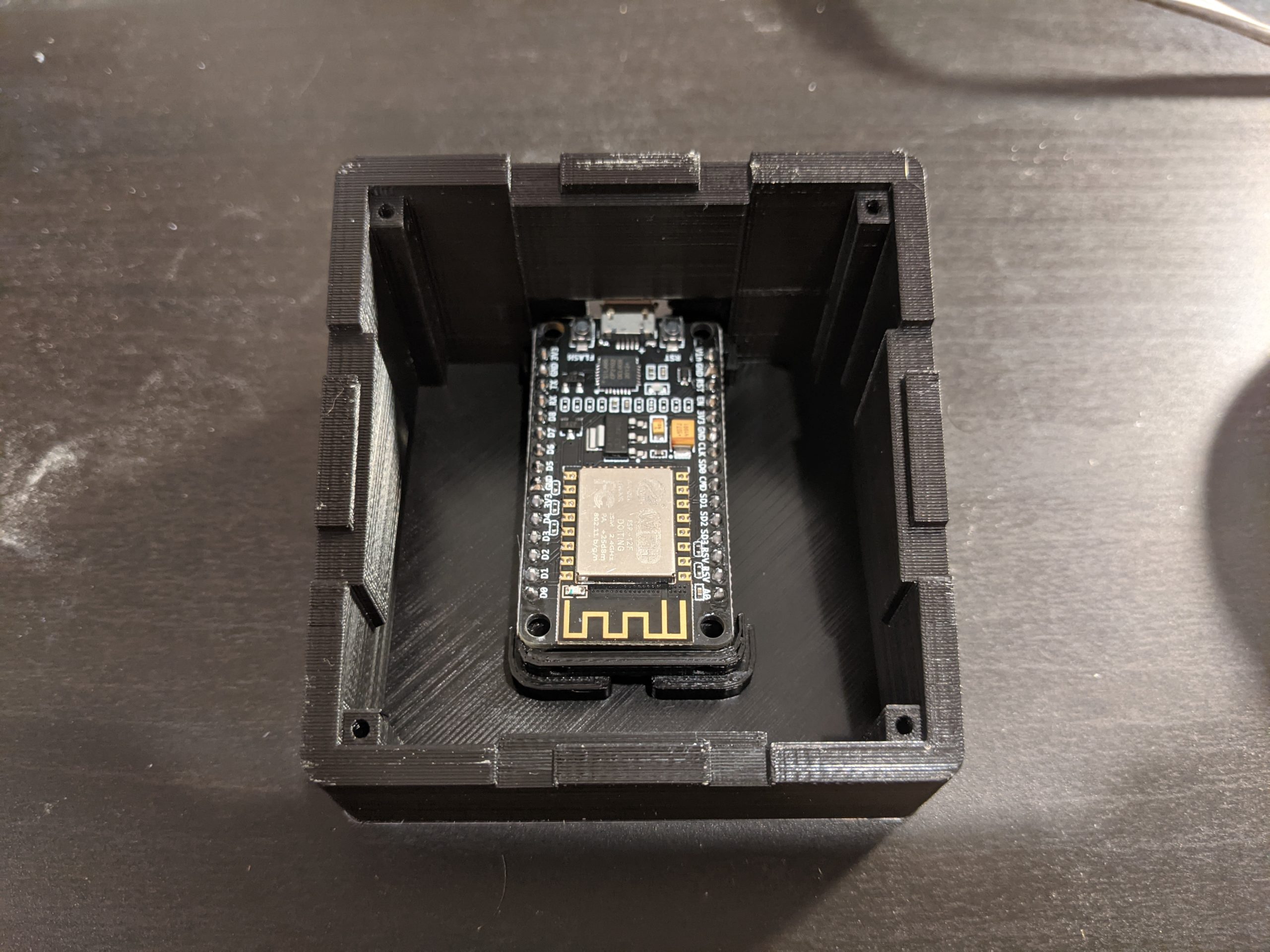
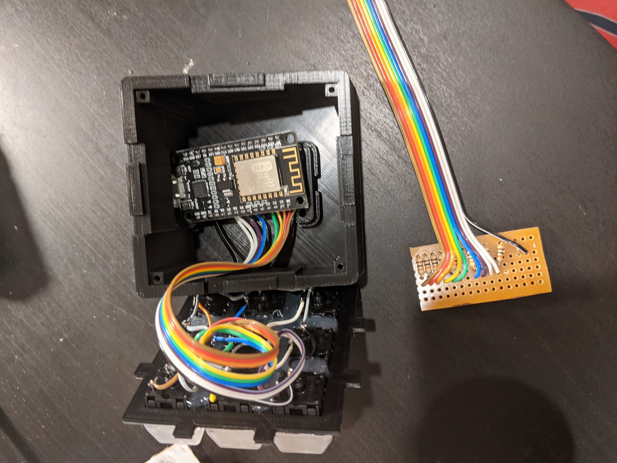
Test fitting everything into the case. I also included the protoboard for scale which isn’t needed anymore in the new design for scale.
Using Windows this Time Round
Running into a hardware failure on the Linux machine I used for development on the first generation, I had to fall back on my windows workstation. So setting up a brand new development environment.
Following the basic instructions from ESPHome worked. I installed python 3 and used pip to install esphome and wheels following the directions. Once I had that ready, I needed to install the driver for the ESP board. Once the driver was installed, I could start flashing firmwares.
Debugging
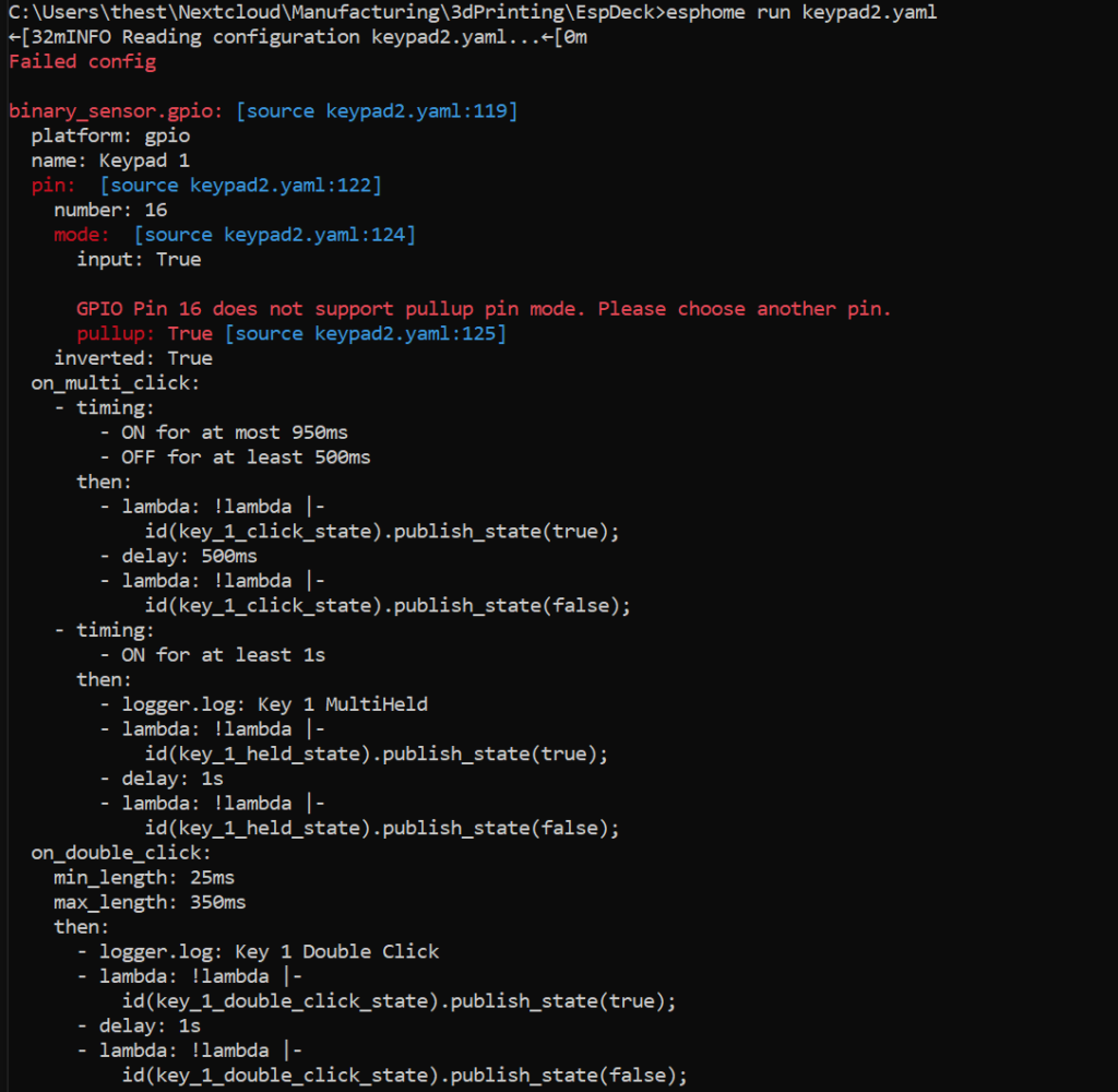
Once I had the development environment up and running, I loaded the initial configuration into the ESP and found that I had a few problems to work out. The first is that GPIO 16 doesn’t support a pull-up resistor in the configuration.
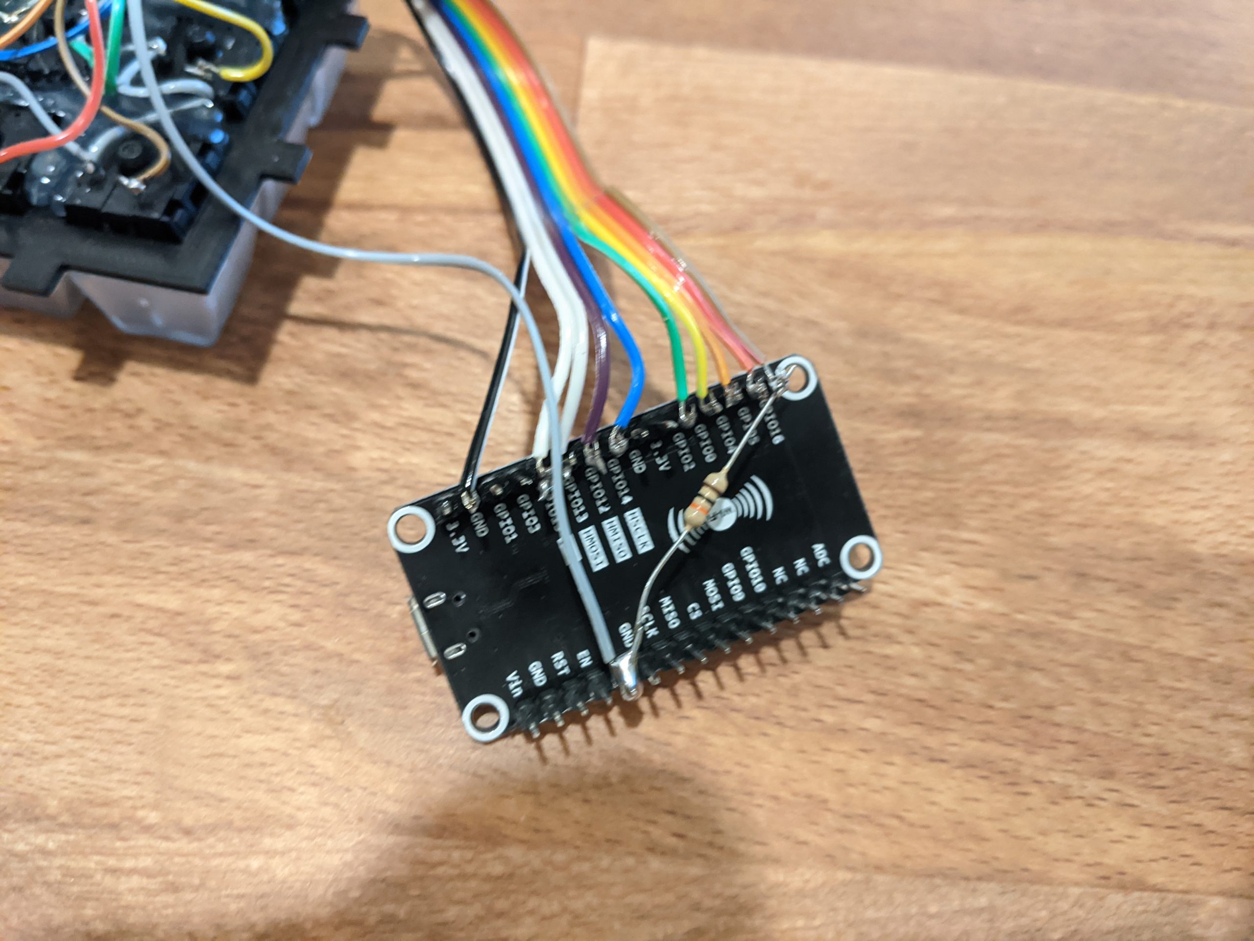
So I had to change keypad one to use an external pull-up resistor which I soldered to the bottom of the ESP8266. This let keypad 1 work, however I did run into a second issue as well.
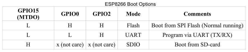
To get GPIO 15 working, I tried adding an external pull-up resistor, however this kept the ESP from booting since it tried to boot from SD (which there is none). Since the internal pull-up and external pull-up both fail for the basis, the input has to be opposite the others. GPIO 15 needs to be normally low with the button pulling it up.
With both of these fixes in place and wired, we can finally see the final layout.
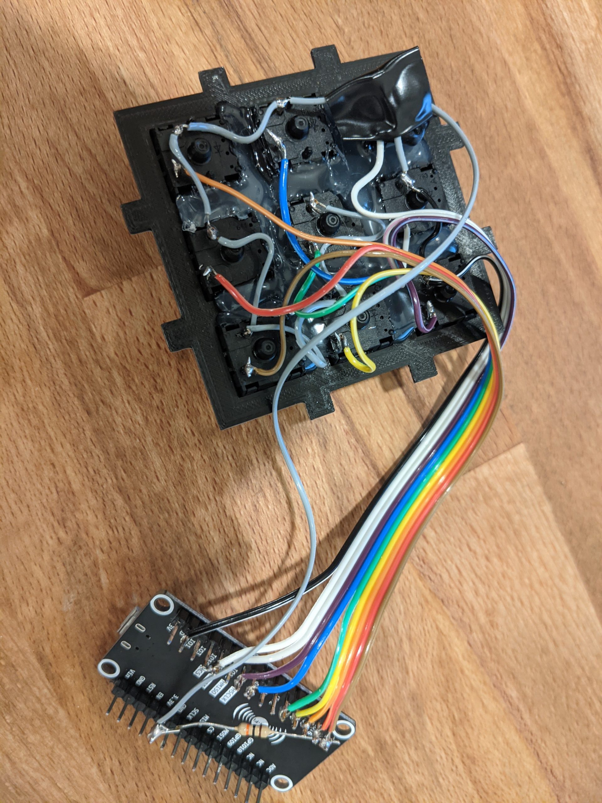
With the wiring completed, it was time to mount it in the case. I found a few screws that fit the holes and ESP board.
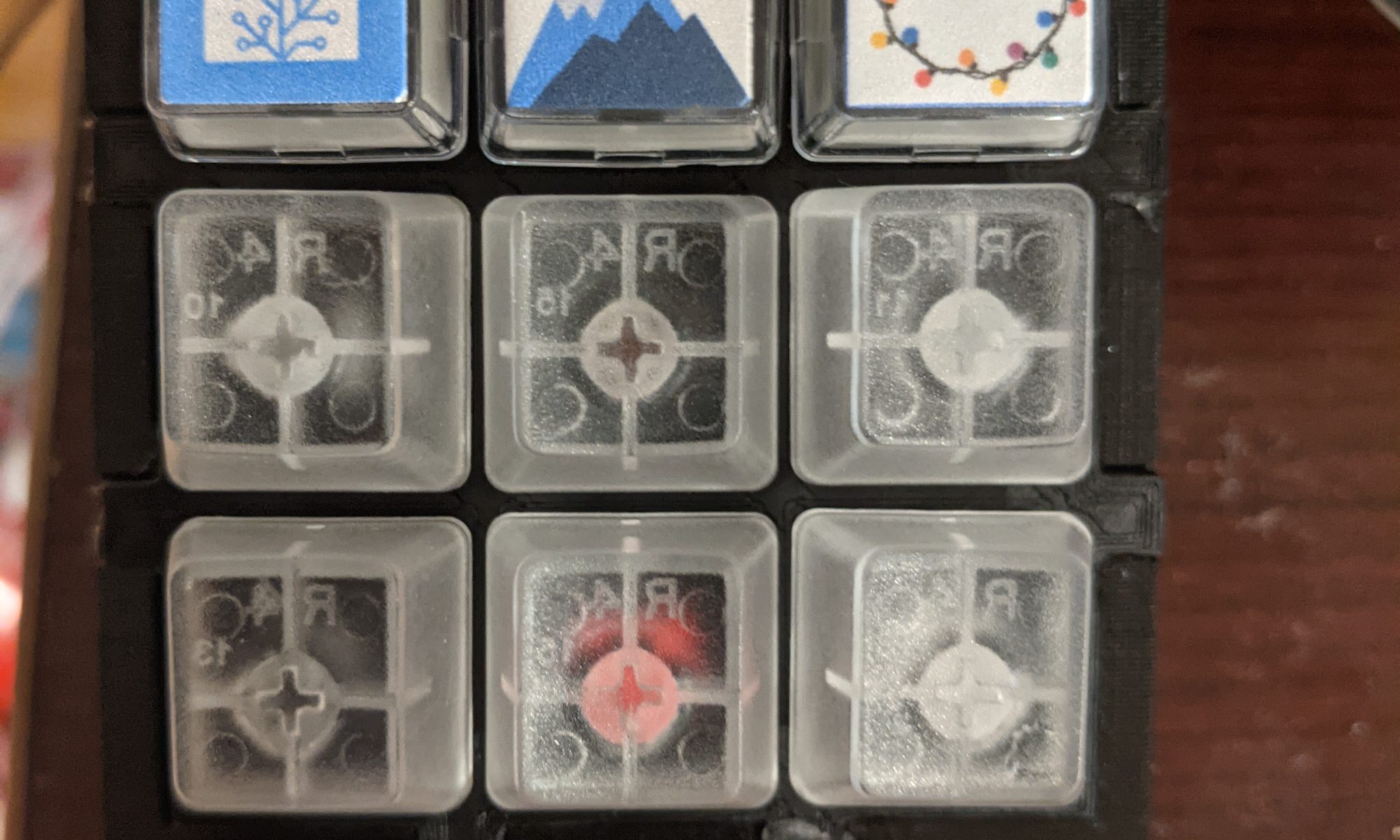
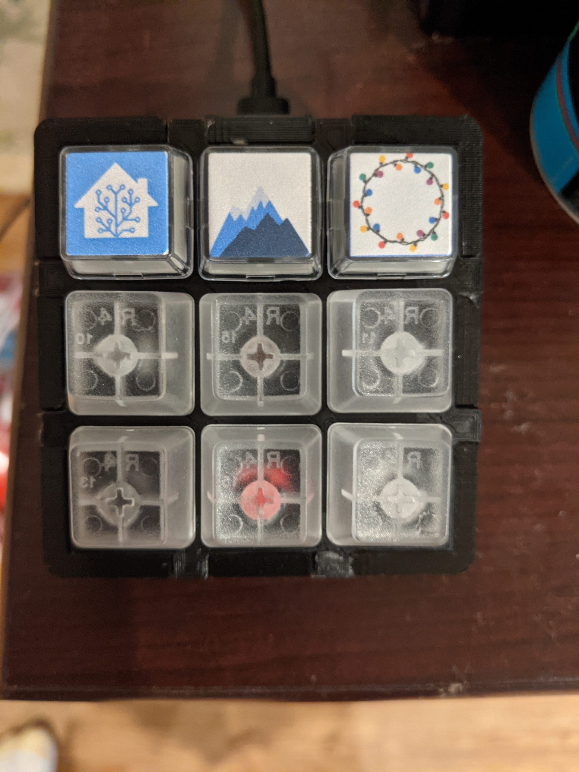
One final step to make it easier to identify which keys are for which function, some relegendable key caps. I’ve only put 3 functions on it so far, so those are the ones with the custom keys, home mode, away mode, and toggle Christmas lights.
Configuration
With all the switches now pulling down the input IO, the configuration can be the same for all switches, however there are a few extra pieces to handle the normally high input now.
  - platform: gpio
    name: "Keypad 1"
    pin:
      number: 16
      mode:
        input: true
      inverted: true
    on_multi_click:
      - timing:
        - ON for at most 950ms
        - OFF for at least 500ms
        then:
          - lambda: !lambda |-
              id(key_1_click_state).publish_state(true);
          - delay: 500ms
          - lambda: !lambda |-
              id(key_1_click_state).publish_state(false);
      - timing:
        - ON for at least 1s
        then:
          - logger.log: "Key 1 MultiHeld"
          - lambda: !lambda |-
              id(key_1_held_state).publish_state(true);
          - delay: 1s
          - lambda: !lambda |-
              id(key_1_held_state).publish_state(false);
    on_double_click:
      min_length: 25ms
      max_length: 350ms
      then:
        - logger.log: "Key 1 Double Click"
        - lambda: !lambda |-
              id(key_1_double_click_state).publish_state(true);
        - delay: 1s
        - lambda: !lambda |-
              id(key_1_double_click_state).publish_state(false);
We just have to GPIO pins that need custom configuration from the rest. Starting with GPIO 16 which doesn’t have an internal pull-up.
  - platform: gpio
    name: "Keypad 1"
    pin:
      number: 16
      mode:
        input: true
      inverted: true
    on_multi_click:
.................................
The last pin is GPIO 15 which can’t use the default high and pull-down switches. This instead is defaulting low with the switch pulling up the value.
  - platform: gpio
    name: "Keypad 9"
    pin:
      number: 15
      mode:
        input: true
        pullup: false
      inverted: false
    on_multi_click:
........................
Gen3 and Onwards
I’ve been given some ideas and added some of my own as well to the list. For now I’ll be sticking with the two keypads I’ve made so far until I see a need to start making more, in which case I’ll start working on more advanced designs.
- StreamDeck / FreeDeck style LCD screens on each key
- Battery powered
- Zigbee based
Though in reality, generation 3 will probably just be optimizations to the design, especially to the case and installation, and I will likely look into a better way to handle my YAML without copying / pasting things 9 times.
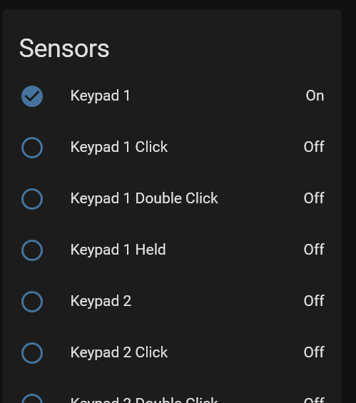
Conclusion
I’m very happy with the outcome of the second generation EspDeck. The quicker, simpler build combined with the nicer case made the entire experience much better. Integrating the a unit into home assistant was also smooth though now I have quite a few binary sensors all named similarly, so maybe I’ll need to dig into making those more unique for next time as well. I still have a lot of ideas I could use to make these better, but I’ve certainly scratched the itch I had.