The time has come for a new iteration of the EspDeck. This time it’ll include a few new features, and a new form factor. The new version will include all the features of the Tag Reader, original EspDeck, and a rotary encoder.
The original 9 key pad will still be supported, this will just provide another option if the features are needed. The main use case of this new version is for controlling multi-room audio. The keypad will provide inputs for joining and leaving speaker groups etc, rotary encoder for volume on that rooms speaker, and the NFC reader will read cards for various things to play over the speakers (music, playlists, maybe even podcasts or audiobooks).
Features
- 4 models with varying features, 2 models being featured right now
- 9 keys (8 key switches, 1 rotary encoder press)
- Rotary encoder
- Buzzer
- NFC Reader
- WS2812 LEDs backlighting the keys, individually addressable by Home Assistant
- Single press, double press, and press and hold on every switch
Parts
- ESP32 DevKitv1
- 1 x NFC Card Reader
- 1 x Piezo Buzzer
- 4 x Rubber Feet
- 8 x Mechanical Key Switches (RGB variant / clear plastic bodies)
- 8 x Relegendable Keycaps
- 1 x Rotary Encoder
- 1 x Knob
- 8 x WS2812 LEDs (60 LED per Meter, 16.5mm interval)
- 2 x 100 Ohm Resistors
- 2 x 1 uf Capacitors
- 4 x M2 Heat Set Inserts
- 4 x M2 Screws
Initial Design
The rotary encoder replaces one of the switches in the 9 key pad (since it has a click switch when pushing it in). We also add the buzzer, NFC reader, and WS2812 LED as new additions alongside the rotary encoder
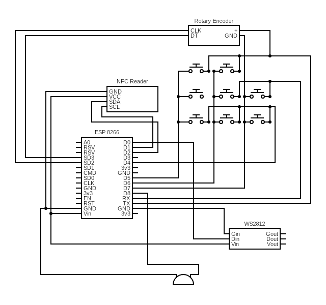
I did a few drafts of the design like the one above, these changed pin selection on the ESP8266, component layouts, etc, then I ran into the major limitation that completely stopped me from using an ESP8266, the amount of internal flash.
I threw together some demo software to try things and it requires just over 1MB of flash in order to run OTA updates, which the 8266 has ONLY 1MB of flash. So in this case, I can flash my software onto it initially, but I can’t update it without first flashing a minimal firmware, followed by the new firmware. I did a few things to see if I could work around this, and I found that I could remove the logger, and then I could run OTA updates, however debugging without the logger is not a fun thing to do, so I decided to go to an ESP32 with more than 1MB of flash.
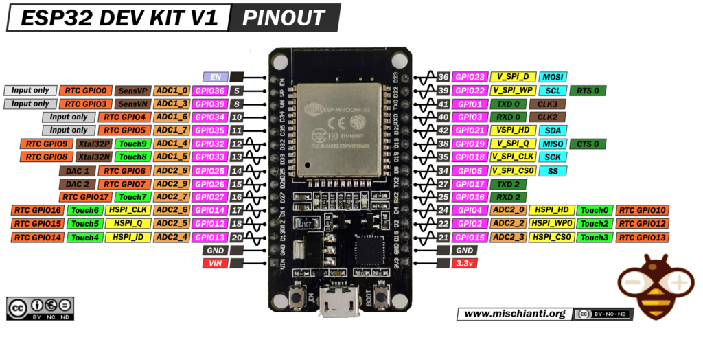
ESP32 Based Design
I found the ESP32 dev kit v1 was a good one to start with, it had mounting holes I can use to screw it into my case, 2MB flash, and a decent amount of IO to make use of. I started out with research on the pinout of the ESP32, picking GPIO to use for my sensors that had all the capabilities I need. Below is the pin out for the ESP32 devkit v1 that I used for reference. All the GPIO pins I used are in the substitutions block in the ESPHome config to be easily swapped to a different controller if needed, and are also shown on the circuit diagrams.
Rotary Encoder Design Changes
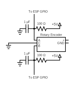
While researching rotary encoders and how to properly include them in my circuit, I found a blog post talking about the best way to incorporate them while cleaning up the signal to the ESP micro controller. This included a circuit using two capacitors with pull-up resistors, that way when the rotary encoded rotated through, grounding the signal pins, the capacitors would take longer to discharge, keeping the pin high for a slightly delayed amount of time while also preventing any jumping in the signal that would cause incorrect incrementing from the encoder.
I did experiment with forgoing the external pull-ups + capacitors in my rotary encoder, and I found that home assistant would jump heavily around when rotating the knob one direction, less so the other direction. This asymmetry would become quite difficult to navigate around without either a lot of software to clean the signal or hardware to do so. I’ll try out adding the hardware to see how that goes.
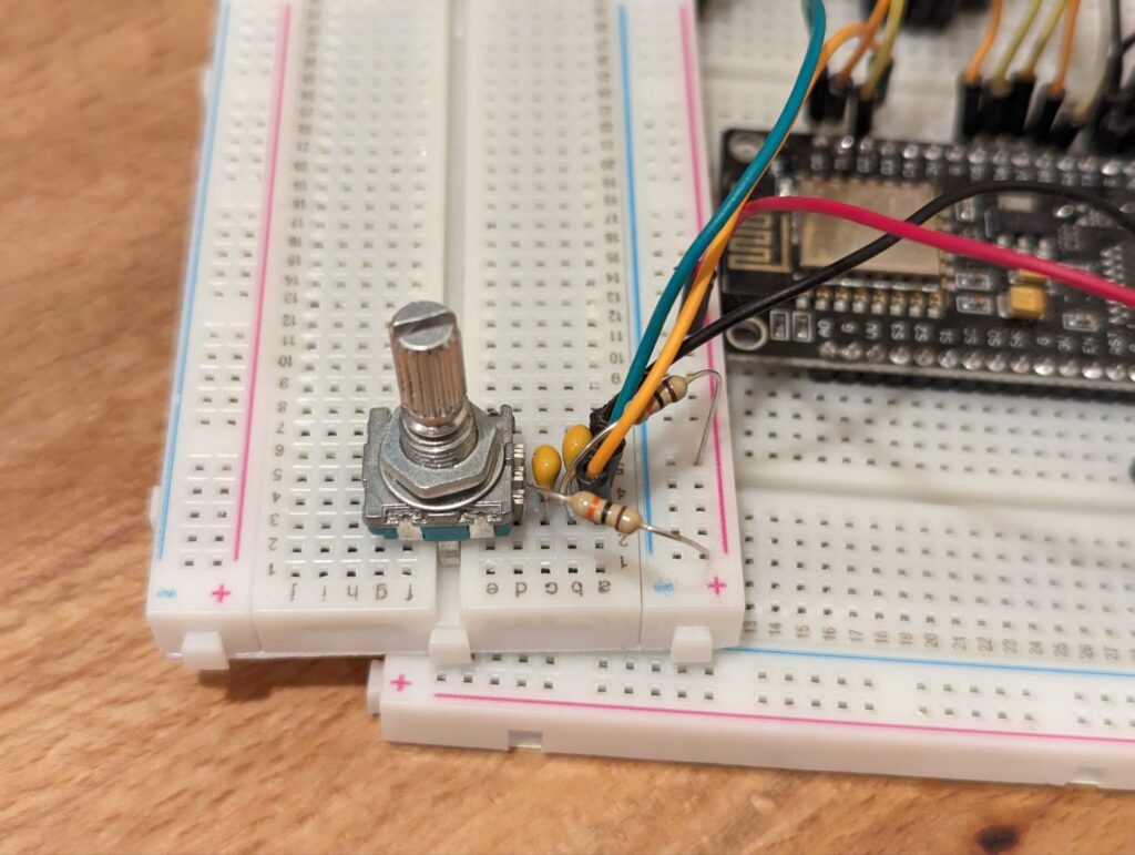
I built a prototype circuit using the provided design, and found I was still having issues. I accidentally pulled 10 ohm resistors to build the circuit (my resistor trays were mislabeled). This almost worked however, the circuit counted up well without any major jumping, however counting down was problematic on the encoder. I tried the suggested 10k ohm resistors and had my rotary encoder only counting up, never counting down. I then decided to split the difference, I tried 100 ohm resistors and everything worked perfectly with them. Rotating the encoder left and right worked equally well, I could even spin it quickly both directions without the counters jumping the opposite directions.
With this additional part of the circuit designed and prototyped, I had basically the entire NFC Deck circuit ready to draw out.
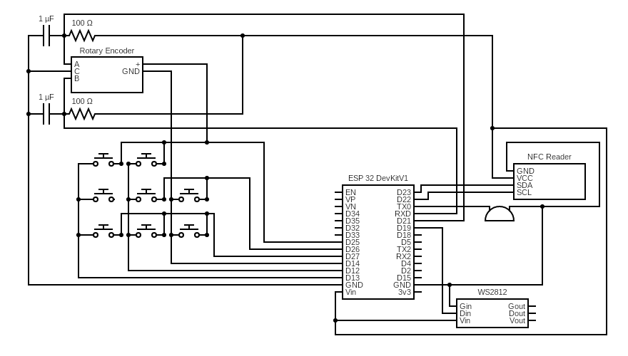
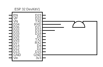
I also split up the circuit into smaller digestible pieces. These are split out by component (except the 9 key pad which is kept as one large unit, and includes the rotary circuit too). We’ll start with the simplest part, the buzzer, which just connects to one GPIO pin and ground.
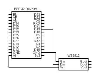
Next we have the LED strip that is backlighting the keys. This needs 5v and data, so we connect it to D19, VIN and ground. We have a small enough number of LEDs that we won’t harm the ESP32 by using it to power the LEDs.
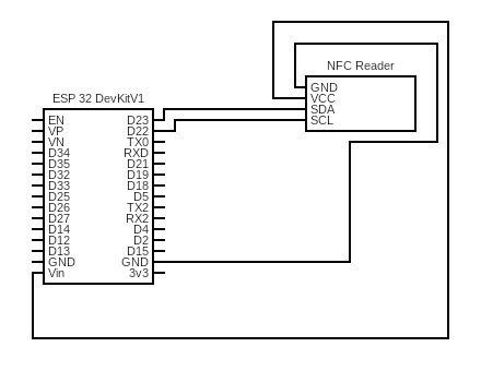
Now we have the NFC reader, this needs two GPIO pins along with power.
We get to the circuit that cleans the signal from the rotary encoder, this is where things get interesting. Each signal pin gets a pull-up resistor and a capacitor between the line and ground, then we just have the middle ground pin on the rotary to hook up.
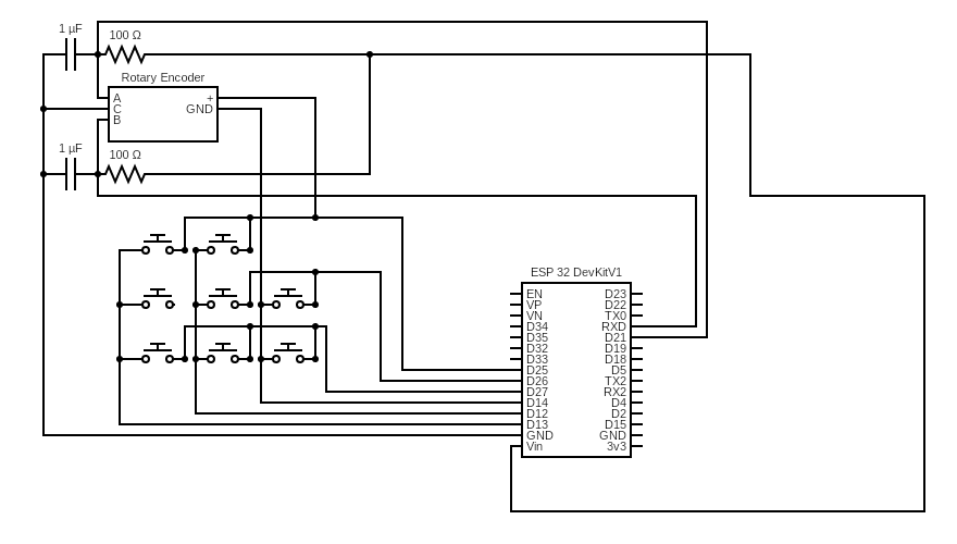
The above rotary circuit can be found in place in the 9 key circuit below. I found it easier to build the circuit first, then add it into the rest of the NFCDeck wiring afterwards.
Case design
The case design is very similar to the basic 9 key EspDeck, just extended in length. The additional length is to give it space for the NFC reader and additional electronics for it. This also lets the tags get close enough to the reader for it to read them.
The will be 4 designs in total:
- 9 key
- 8 key + rotary
- 3 key
- 2 key + rotary
For this first iteration of the design, I’ll just be focusing on the 9 key versions. Once these are done, I’ll start working on the designs for the 3 key iterations. This split in the designs will let me use an expanded keypad where it makes sense, and limit the number of keys where it makes sense to have a smaller number of interactions. Within the two designs, there will also be an option to use a rotary encoder or not.
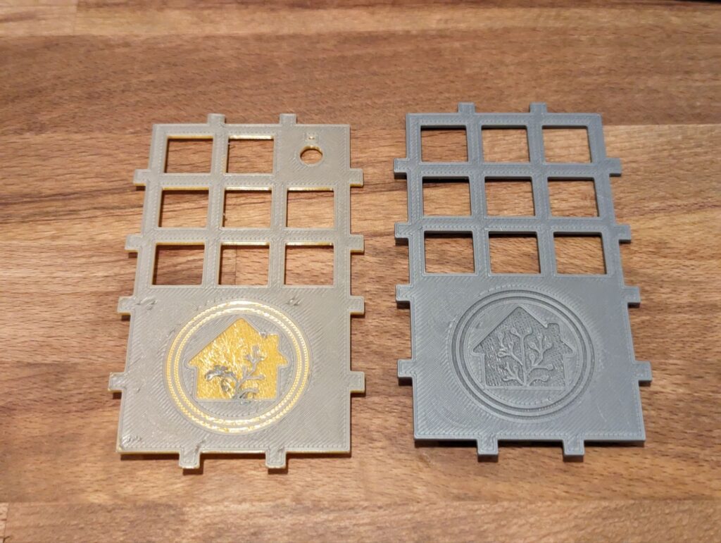
Use a thicker layer height when printing the top plate, 0.16mm or higher. This helps the details come out cleaner in the home assistant logo. Using thinner layer heights has given me more trouble when trying to get those details to print cleanly.
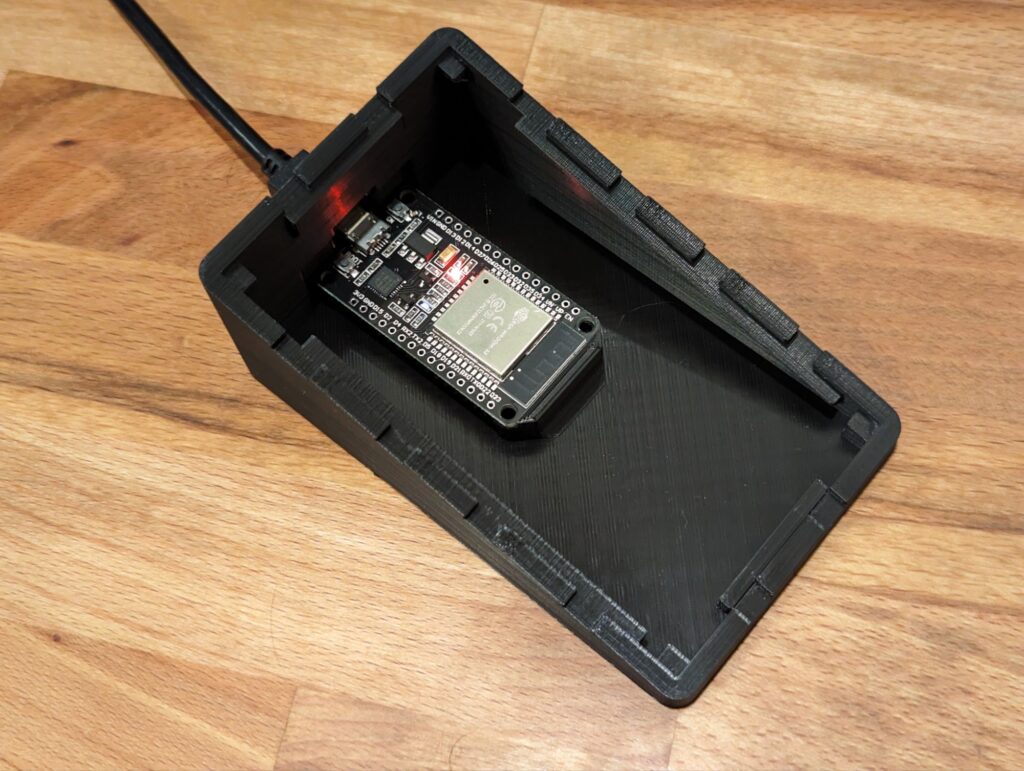
Once I found an ESP32 unit with the right flash quantity and good support from EspHome, I modeled the ESP mount into the case. I printed a prototype to check if everything fit well and it all fit on the first try. All four mounting holes lined up perfectly.
I used a soldering iron to install the heat set inserts. It takes a bit of a delicate touch to keep them vertical and from melting into the plastic too far. The M2 sizing was just about perfect to fit the holes I modeled into the case, though M3 should fit just fine as well.
Assembly
The entire assembly process is outlined below. The general process is to print the parts, and then build and wire the entire top. After that the controller and rotary board can be soldered in, and then everything mounted to the base and hot glued together.
- Print top
- Print case
- Insert heat set inserts
- Mount key switches to top plate
- Mount rotary to top plate
- Solder LED strips
- Mount LED strips to key switches / top plate
- Wire key switches and rotary
- Wire up NFC reader
- Mount NFC reader to top plate
- Attach all the wires to the ESP
- Mount ESP32 to case
- Hot glue in rotary side circuit board
- Hot glue top on
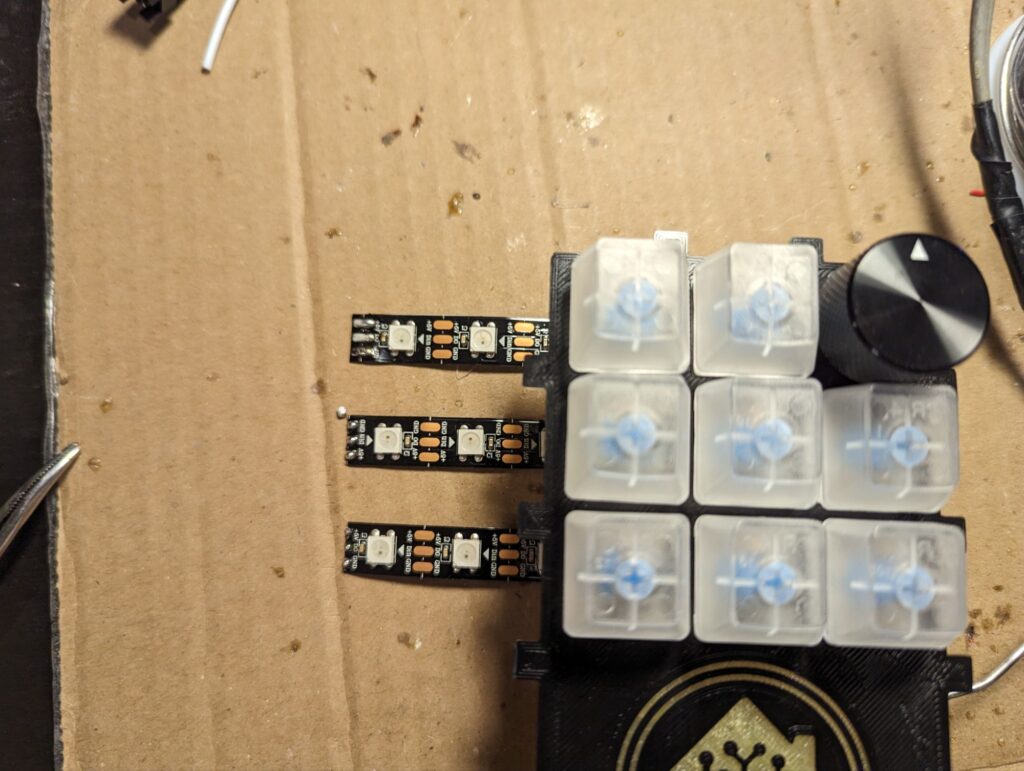
Once I had the key switches and rotary mounted to the top plate, I started working on the LEDs for the backlighting. I have a few different LED strips hanging around from other projects I’ve assembled over the years, so I went to those first to look at different LED densities so that I could hopefully find one that gave me the minimum amount of work to install the backlighting. This ended up being the case with the 144 LED/m WS2812 LEDs which lined up with three keys in a row without issue. If there were more keys, this wouldn’t have worked out since it wasn’t lining up perfectly, but in this case, it works well enough for my situation.
I used the top plate to line things up for spacing the LED strips and then taped them to my soldering mat. This way when I cut the connecting wires to length and soldered them in place, I’d have approximately the right spacing built in.
When soldering the LED strips together, make sure to keep an eye on the input and output sides of the strips. Connect your DIN to DO and your connection to the ESP32 should be to the first DIN in the series.
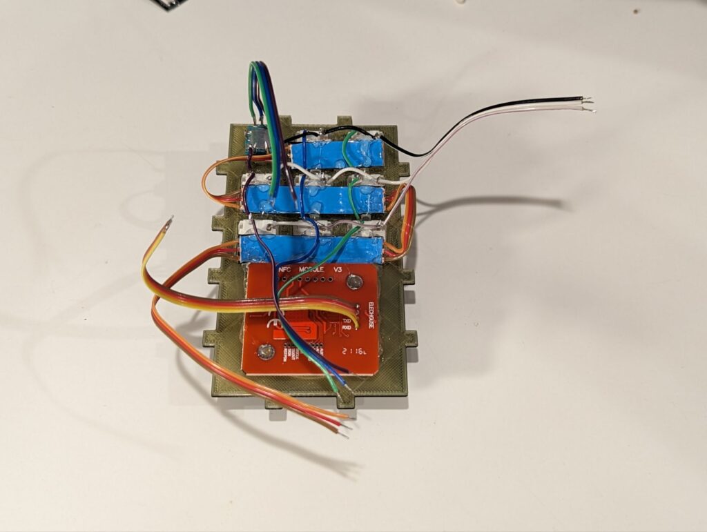
Once the LED strip was hot glued in place, it was time to write the key switches and rotary button into the matrix layout needed. This will take 6 wires, one for each row and column. I like stripping the middle of my wires to solder into the middle pins, this way I don’t have to splice as many wires, but any method will do and this circuit is forgiving.
Make sure you set the dip switches on the NFC reader BEFORE you mount it, or just mount it upside-down (make sure your wiring is coming out the right side for your mounting too).
I may like to strip the middle of wires a bit too much at times, but it’s so convenient when going between things like key switches. It does have a downside at times of potentially damaging the wire in a way you can’t entirely see. After my initial assembly and soldering the cables to the ESP this wire broke. I only noticed it was broken by that column of keys didn’t work. I went through and started investigating why, if I had tried to use a mode on a GPIO pin it didn’t support or another reason, luckily it wasn’t long till I found the broken wire and was able to fix it quickly.
I built the rotary encoder circuit on a small circuit board. It needs power, the signal in from the rotary, and the signal back to the ESP. Afterwards I wired it into the ESP32 and the rotary encoder to hook that into the entire system.
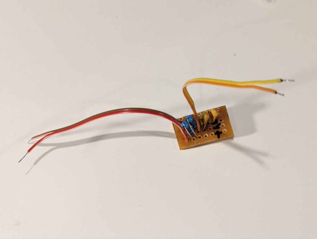
The esp32 can be screwed into place with the heat set inserts. This gives it a solid mount for when you plug and unplug the USB power to the keypad. I also hot glued the side circuit board into the corner of the case for the rotary encoder. If you don’t have heat set inserts, then just find some screws that thread into the plastic well, I built 3 keypads doing this and they hold up well.
That’s basically the whole assembly, with all the internals in the case, it’s time to wiggle the lid on, trying to keep any wires from crimping between the case and lid and then hot gluing the lid on top.
Oddities to Note
I did notice something interesting when I went to try out the keypad for the first time after wiring it, other components in my design worked, but the entire 9 key pad didn’t. Now I’ve had rows or columns not work due to broken wires or GPIO without internal pullups, but never the entire pad until now. This however did seem to be an internal pull-up problem, as once I flipped the rows and columns in my configuration and re-uploaded it, everything started working again. The below configuration is the one that didn’t work at all.
matrix_keypad:
  id: espdeck_keypad
  rows:
    - pin: $nine_key_pin_1
    - pin: $nine_key_pin_2
    - pin: $nine_key_pin_3
  columns:
    - pin: $nine_key_pin_4
    - pin: $nine_key_pin_5
    - pin: $nine_key_pin_6
However the next configuration works 100%.
matrix_keypad:
  id: espdeck_keypad
  rows:
    - pin: $nine_key_pin_4
    - pin: $nine_key_pin_5
    - pin: $nine_key_pin_6
  columns:
    - pin: $nine_key_pin_1
    - pin: $nine_key_pin_2
    - pin: $nine_key_pin_3
My going theory is that this has to do with which pins can work with internal pullups turned on or not. I could have wired it differently for the rows/columns, but since I do only have 9 keys, and they’re in a square layout, there’s no real reason to. The key numbers can be corrected in software.
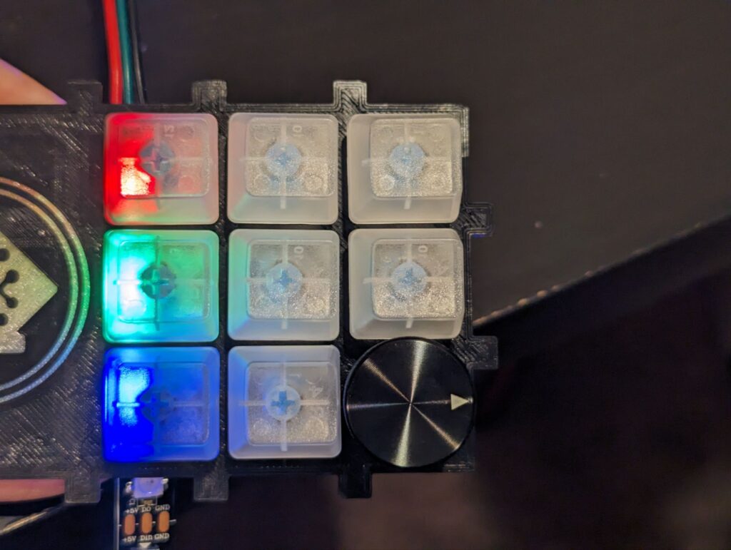
Lighting The Keypad
To setup the lighting so that home assistant can address each key light individually, I made use of the ESPHome light partition component. This let me split the entire strip up into individual LEDs for easy use in automations etc.
light:
  - platform: neopixelbus
    variant: WS2812
    pin: $neopixelbus_pin
    num_leds: 8
    flash_transition_length: 500ms
    type: GRB
    id: light_strip
    name: "${friendly_name} LED"
    restore_mode: ALWAYS_OFF
  - platform: partition
    name: "Key 1 Light"
    id: activity_led
    segments:
      - id: light_strip
        from: 0
        to: 0
  - platform: partition
    name: "Key 2 Light"
    segments:
      - id: light_strip
        from: 1
        to: 1
  - platform: partition
    name: "Key 3 Light"
    segments:
      - id: light_strip
        from: 2
        to: 2
Now the docs for the light partition do say to not split the LED strip up into individual LEDs using the feature as it uses a lot of resources, but we’re also not using that many lights, since there’s only 9 of them max in this design, so we’re going to do so anyways.
There is also a funny when the whole light strip settings are used in addition to the per LED setting. If I have on 2 of my 9 keys with specific colors, and I turn on the entire keypad light, the individual keys will follow the strip setting, and if I turn off the entire keypad light, now ALL keys will turn off, including the two I turned on before. Home Assistant will still think these two lights are on though. This leads to an inconsistent state between home assistant and the lights, and even possibly EspHome’s state and the actual light state.
Rotary Debounce Filter
Even though I did add the side circuit board with a filter for the rotary encoder that cleans up the signal significantly, I still decided to add a debounce filter to it in the software as well. The debounce filter helps keep from getting arbitrary values out.
sensor:
  - platform: rotary_encoder
    name: "Rotary Encoder"
    pin_a: $rotary_pin_a
    pin_b: $rotary_pin_b
    publish_initial_value: true
    filters:
      - debounce: 0.1s
This combined with the circuit made for a pretty good system, though a fast spin can still act up on the rotary encoder. The debounce filter can be added onto the keypad keys as well if it’s needed. I haven’t had any problems with my 3 EspDecks that I have made so far, none of them using debounce.
Pointers
When working on things, do remove the knob from the rotary. The beautifully machined surface on top of mine picked up gunk (flux) from my soldering mat like its going out of business. Cleaning it out of all the grooves is also a massive pain to do.
Make sure the labels in your resistor box don’t move, otherwise you might end up using 10 ohm resistors instead of 10k ohm.
When hot gluing the cap down, wait for the edges to cool a bit before cleaning them up, I tried to wipe the hot glue away before it solidified and it just got into the layer lines of the print and made things a lot uglier.
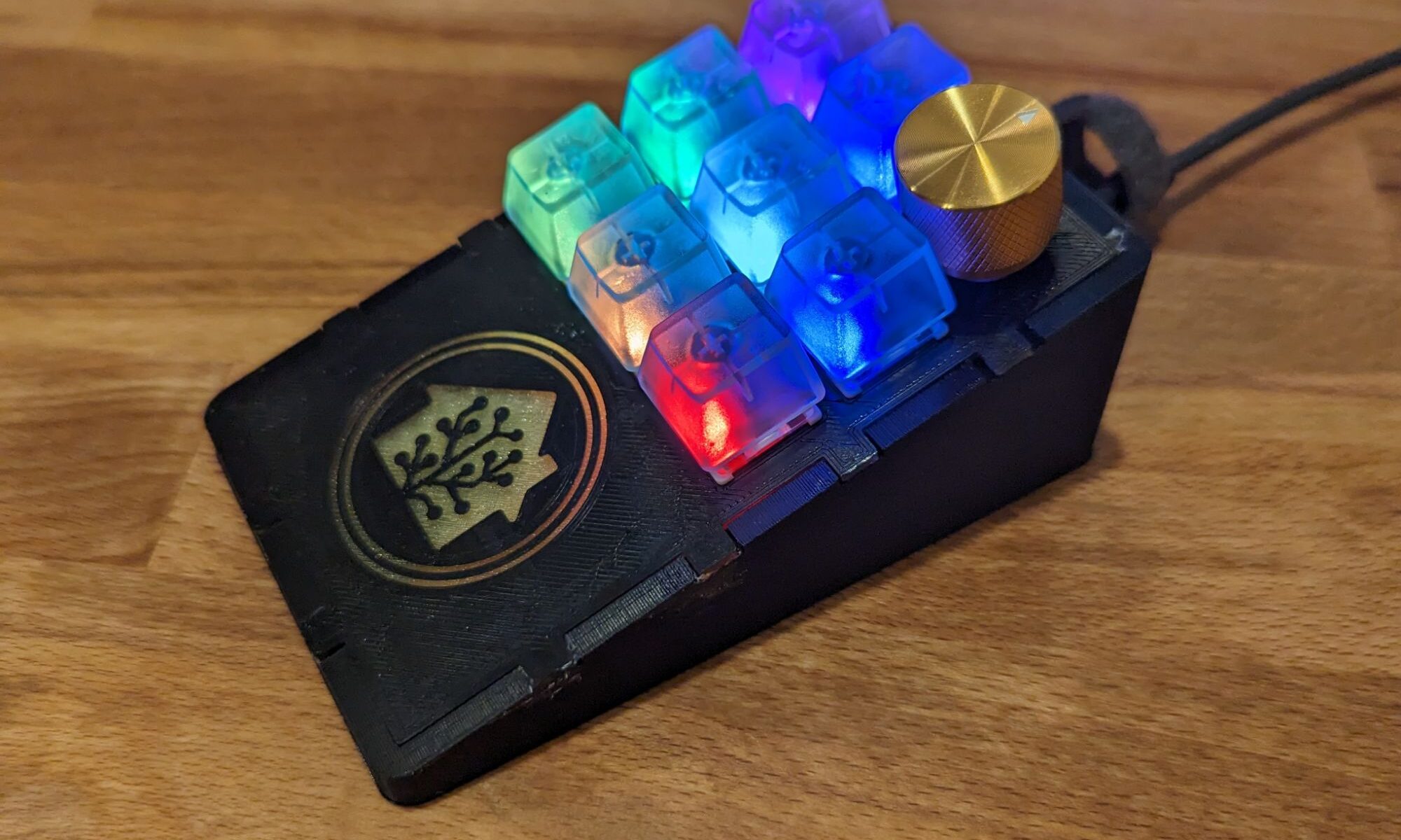
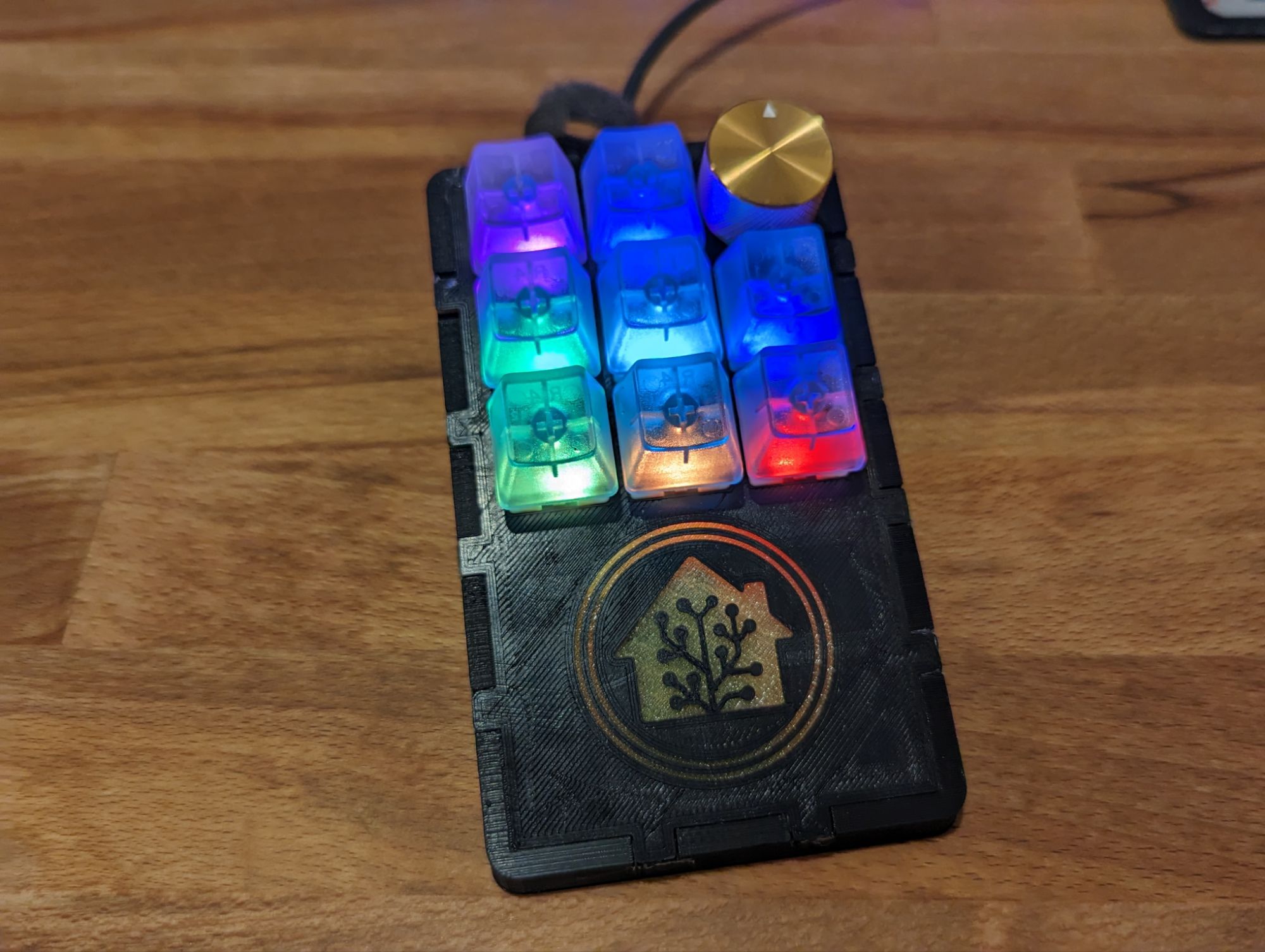
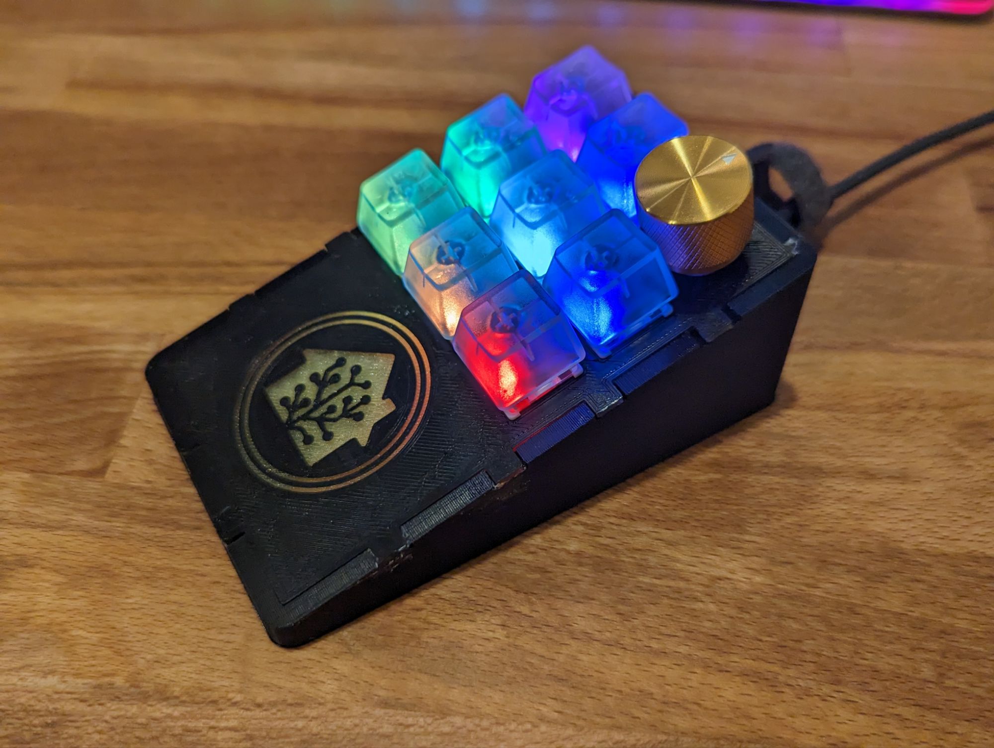
Finished Product
The final product came out pretty well. Some details could’ve been done a bit better in my build, but overall the finished product is solid. I’ve got it set up already to get some lighting notifications, and trigger various automations. I don’t have the rest of the home audio setup ready, so I don’t have the NFC reader and rotary encoder in use yet.
I also want to give a shout out to the adonno Tag Reader. I made use of their configurations for controlling the NFC reader, and buzzer in the NFC Deck. That part of the software is the most complex part of it, and they’ve done great work on that implementation.
Potential Future Design Changes
Use heat set inserts to mount the keypad plate down to the base rather than using hot glue. This should probably make use of 6 screws, the 4 corners plus two in the middle.
Resources
- NFC tags in home assistant
- Adonno Tag Reader GitHub repo
- EspDeck GitHub Repository
- Blog talking about rotary encoder circuits
- Rotary Encoder EspHome Documentation
- Rotary Encoder Volume Control Knob
- Forum Posts talking about rotary encoders
- Light Partition EspHome Documentation
- Rotary Encoder How To