I’ve been working on getting air quality measurements going in and out of my house, however there are a lot of cloud connected sensors out there. I wanted these to be all local, though I wouldn’t mind adding to the public datasets for air quality. I ended up coming to AirGradient as the option that I decided to use, these use all open hardware and can be flashed with the custom AirGradient firmware, or with EspHome. I went the DIY route as well to save some money (and I’ll be customizing them a bit too).
The AirGradient Saga
(also my first attempt at linking around a multi part post that’s getting additions over time)
- Making the AirGradient DIY
- Adding an LPS22 to AirGradient and Building a Custom Sensor in EspHome
- Adding TVOC to the AirGradient
- The Indoor Air Quality (UK) HACS Integration and Sensor
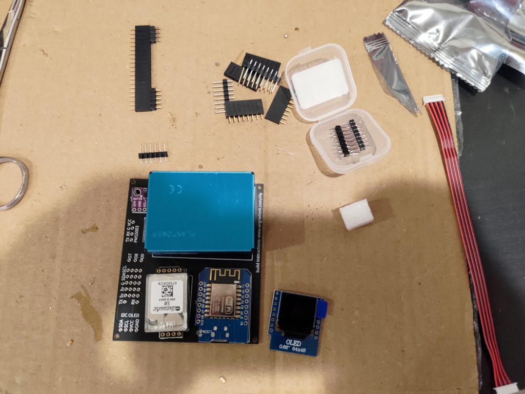
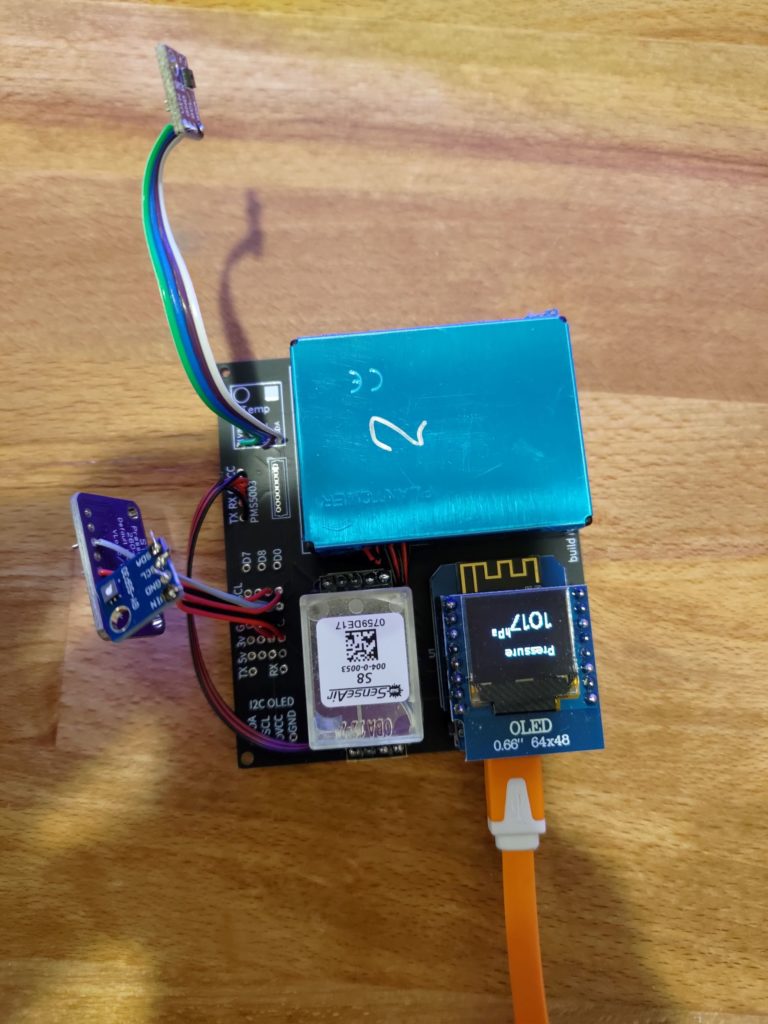
Parts in the Box
- Circuit board
- D1 mini espressif microcontroller
- SHT30 temperature sensor
- SenseAir S8 CO2 sensor
- PMS5003 particulate matter sensor
- Display shield
Assembly
The assembly process is relatively straight forward.
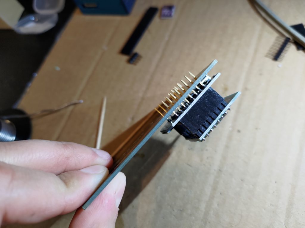
I used a breadboard to line up and hold the pin headers in place when soldering them to the OLED display. This worked out well to make sure the pins were all lined up.
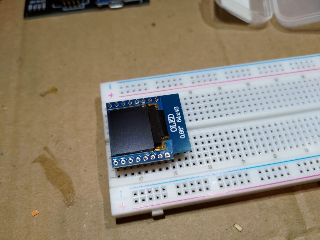
I flipped over the OLED display and added the pins to the sockets for the ESP board. I then slid the D1 mini onto the pins to solder it into place. The OLED display helped support the other side and keep everything straight.
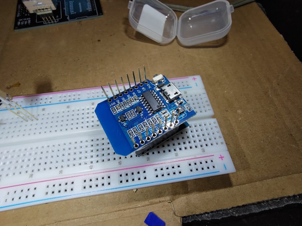
With the pin sockets mounted to the D1 mini. It’s time to mount it to the circuit board. With the OLED, you need to solder the D1 Mini directly on the PCB without the pin sockets, otherwise it ends up too tall and does not fit the enclosure. Also make sure you don’t mount the D1 mini too tight to the circuit board as you could make it impossible to plug in to the micro USB port. I tried to give it a reasonable USB plug spacing from the circuit board.
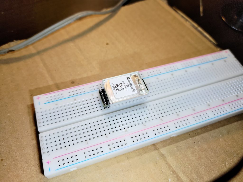
Soldering the sense air sensor is done similarly to the OLED, using a bread board to hold the pins and solder them to the sensor.
With the pins mounted, the CO2 sensor can be soldered onto the PCB. It is important that the bottom side of the CO2 has enough air flow, so make sure the gap is sufficient. I put it on a female pin socket to give it that wider spacing for getting more accurate measurements. I used the pin sockets that came with the D1 Mini, cutting them down to the right size for each side of the sensor.
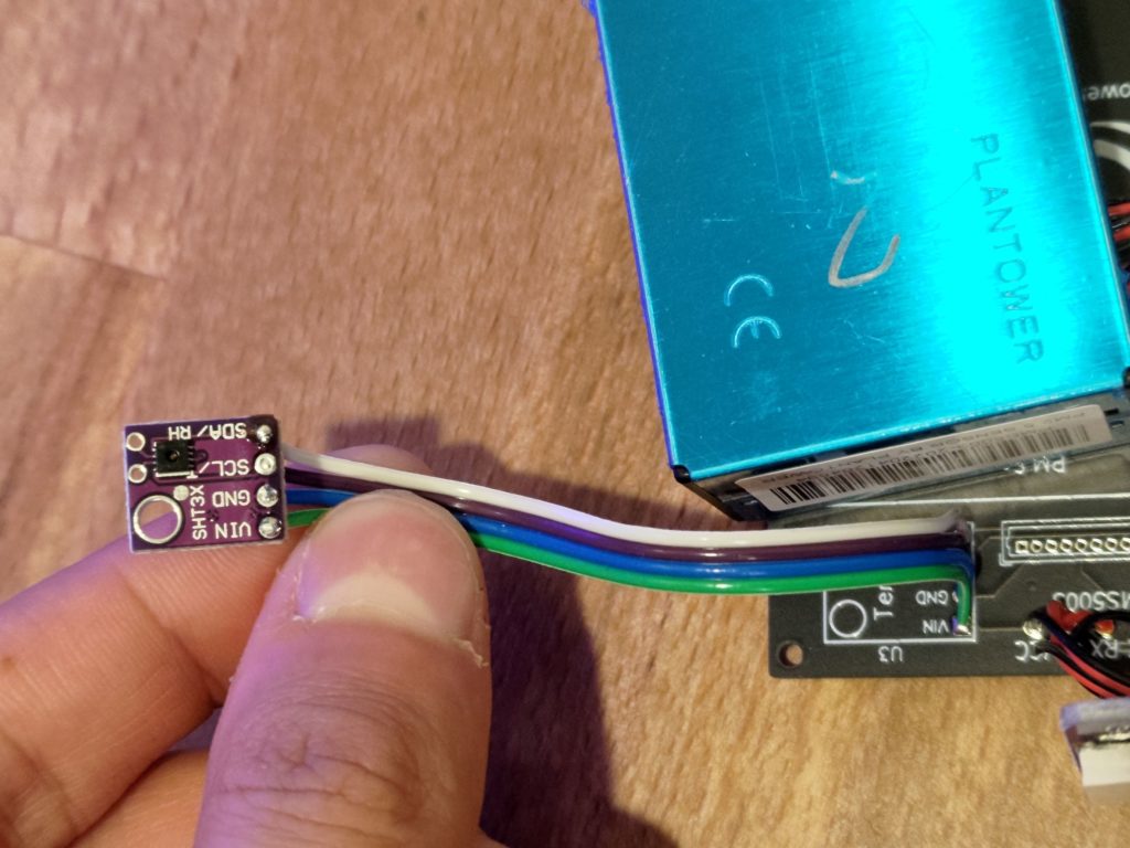
I soldered the SHT30 onto ribbon cables so I could run it into the temperature lighthouse on the original case design, though if I were to do it again, I’d use the pin headers.
If soldering on the pins: Before soldering on the pins, take the time to remove the step up resistors if you plan on adding the TVOC sensor. The resistors are shown in the post about that sensor. To solder the small pins onto the SHT30 module, you can again use the breadboard trick to fix it in place. Only use the 4 pins on the base of the sensors, the other 2 pins are unnecessary.
Then put the SHT30 module through the corresponding holes on the PCB and solder it onto the board. You only need to solder the four pins. No need to do anything with the two pins on the top of the sensor.
The PMS5003 comes with a cable, which we want to cut one end off of to solder to our circuit board. We only need 4 of the wires on the cable, the rest can be cut off or ignored. Double check that if you cut the wires, that you cut the correct ones.
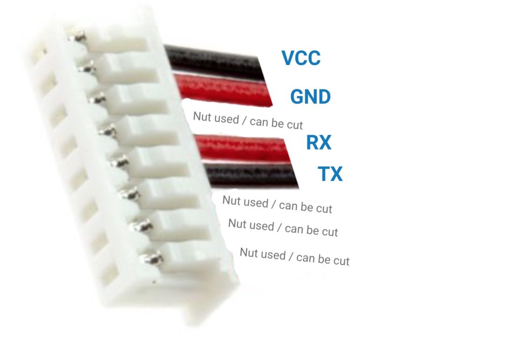
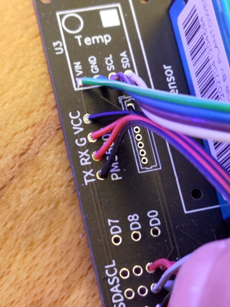
Then solder the cable onto the PCB. Make sure that you solder the correct cable to the correct pin. With the cable soldered in place, connect the other end to the sensor. I ran the cable under the CO2 sensor to avoid giving it too much of a bend. Then the sensor can be double sided taped to the board, or screwed in place.
Programming with ESP Home
I started off with a gist from GitHub for running the AirGradient pro from EspHome. The sensors and configuration are very similar between the two boards, so I figured that would be a good starting point. The biggest differences I had with this gist were the screen settings. I had to do a lot of tinkering to get the right font sizes for legibility and fitting all the data.
The other difference that I ran into was needing to use GPIO pin numbers (ex GPIO4) rather than the digital IO numbers (ex D2). I used the mapping below to get all the inputs I needed for these changes.
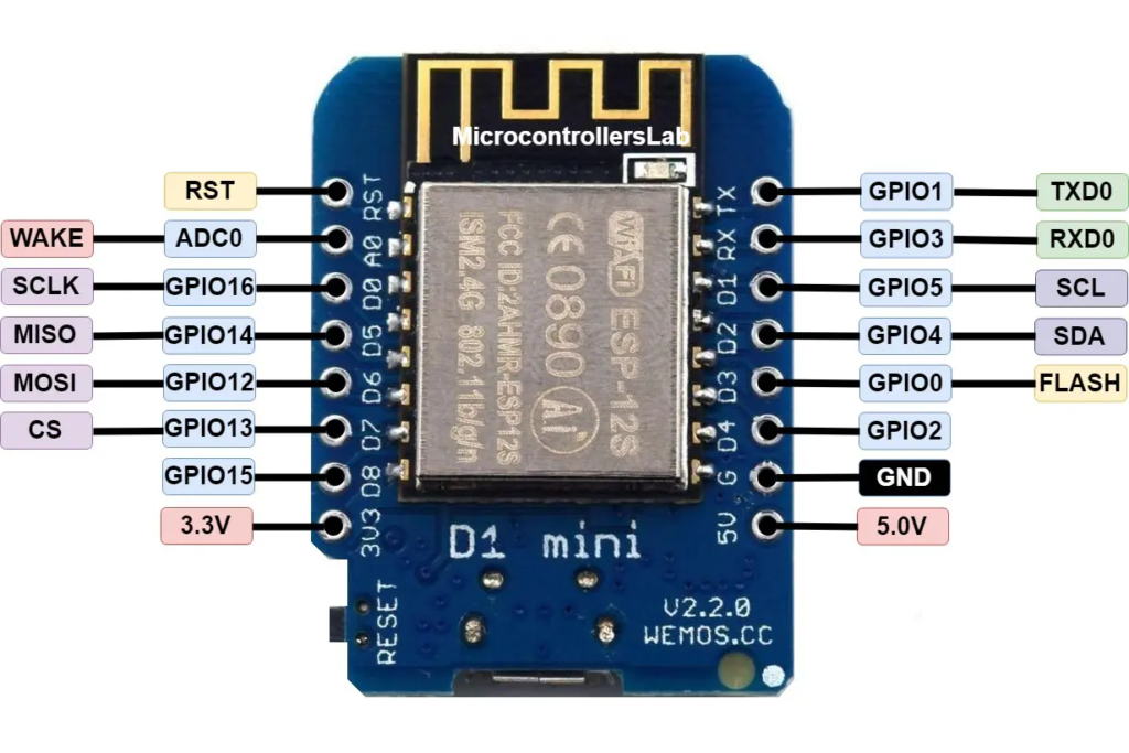
Below is the heart of my EspHome configuration for the sensors, I also uploaded them to GitHub for my full suite of sensors (later on I added a few sensors, so these are included in my GitHub configuration). There you can see the full configuration.
i2c:
sda: 04
scl: 05
uart:
- rx_pin: 14
tx_pin: 12
baud_rate: 9600
id: uart1
- rx_pin: 02
tx_pin: 00
baud_rate: 9600
id: uart2
sensor:
- platform: sht3xd
temperature:
id: temp
name: "Temperature"
humidity:
id: humidity
name: "Humidity"
address: 0x44
update_interval: 5s
- platform: pmsx003
type: PMSX003
uart_id: uart1
pm_1_0:
name: "Particulate Matter <1.0µm Concentration"
id: pm10
filters:
- sliding_window_moving_average:
window_size: 5
send_every: 5
pm_2_5:
name: "Particulate Matter <2.5µm Concentration"
id: pm25
filters:
- sliding_window_moving_average:
window_size: 5
send_every: 5
pm_10_0:
name: "Particulate Matter <10.0µm Concentration"
id: pm100
filters:
- sliding_window_moving_average:
window_size: 5
send_every: 5
- platform: senseair
uart_id: uart2
co2:
id: co2
name: "SenseAir CO2 Value"
update_interval: 20s
font:
- file: "font/productsans.ttf"
id: product
size: 18
glyphs: |
0123456789 .
- file: "font/Roboto-Light.ttf"
id: unit
size: 9
glyphs: |
!"%°RPHF hpabmgµ³/
- file: "font/Roboto-Light.ttf"
id: label
size: 10
glyphs: |
HTPCVDOM25 abcdeilmnoprstuxy.
display:
- platform: ssd1306_i2c
model: "SSD1306 64x48"
rotation: "180°"
id: main_screen
pages:
- id: page1
lambda: |-
it.printf(39, 45, id(product), TextAlign::BOTTOM_RIGHT, "%.1f", (id(temp).state * 1.8) + 32);
it.printf(39, 32, id(unit), TextAlign::BOTTOM_LEFT, "°F");
it.printf(5, 2, id(label), TextAlign::TOP_LEFT, "Temperature");
- id: page2
lambda: |-
it.printf(39, 45, id(product), TextAlign::BOTTOM_RIGHT, "%.1f", id(humidity).state);
it.printf(39, 32, id(unit), TextAlign::BOTTOM_LEFT, "%% RH");
it.printf(5, 2, id(label), TextAlign::TOP_LEFT, "Humidity");
- id: page3
lambda: |-
it.printf(39, 45, id(product), TextAlign::BOTTOM_RIGHT, "%.0f", id(co2).state);
it.printf(39, 32, id(unit), TextAlign::BOTTOM_LEFT, "ppm");
it.printf(5, 2, id(label), TextAlign::TOP_LEFT, "CO2");
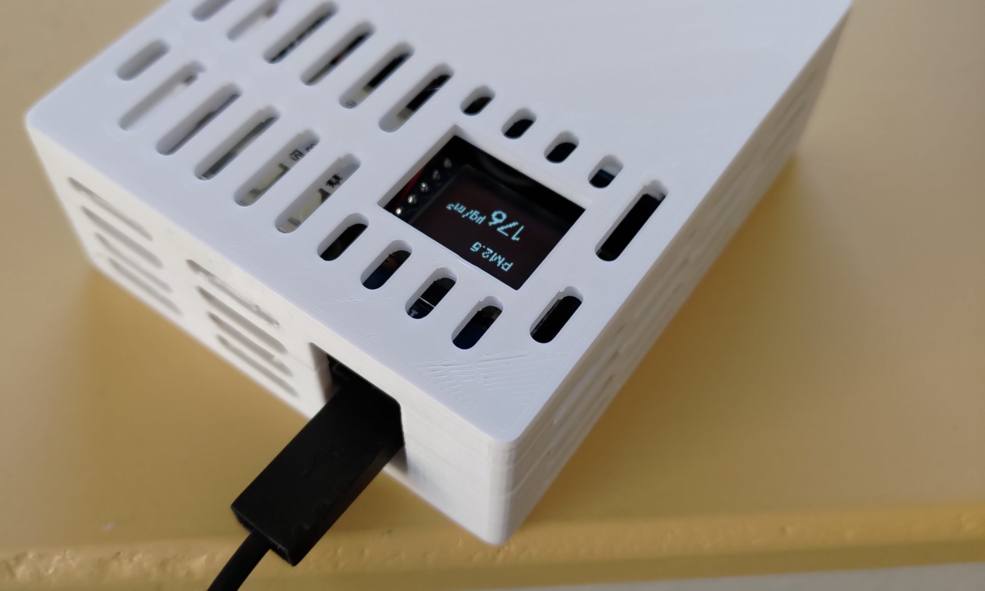
- id: page4
lambda: |-
it.printf(39, 45, id(product), TextAlign::BOTTOM_RIGHT, "%.0f", id(pm25).state);
it.printf(39, 32, id(unit), TextAlign::BOTTOM_LEFT, "µg/m³");
it.printf(5, 2, id(label), TextAlign::TOP_LEFT, "PM2.5");
interval:
- interval: 8s
then:
- display.page.show_next: main_screen
- component.update: main_screen
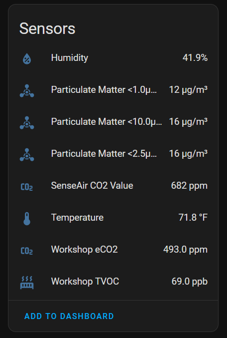
Once I had that done, I hooked things up to home assistant through the esphome integration. Since I was adding some extra sensors as well, you’ll see those shown below, I have some future posts going through that process.
If I make more in the future, I will mount the temp sensors on pins and use this for a case. I will also need to remove the resistors first before mounting them. In my case I used this case with plenty of good ventilation and I also made use of the temperature sensor tower from the original AirGradient case.
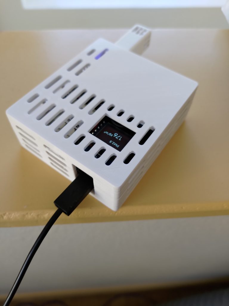
Conclusion
The units all turned out well and output good data that I can now use to tune some following in my house (especially for particulate kicked up by the laser). I’ll be putting the 3 AirGradients I built in various locations for reading data and creating some picture elements cards to show that data.