I found a guide for running WLED on an ESP8266 micro controller to drive individually addressable RGB cables. I thought this would be a fun little project after working with the smart plugs and home assistant automations. Since WLED is another FOSS and cloud-free project, this still fits with my whole fully self hosted smart home ideal. Since no project is fool proof and I have run into small problems when working on the project.
Note: ESP32 boards are more powerful and a more future proof option for WLED, I’ve updated links to point to those now as they should be used instead today. I may come back later and create a new guide for them. Most of this should still be applicable.
Components Used
| ESP32 Dev Board | This board will allow us to connect via WiFi and output a digital signal to our LEDs. The link here is for a 4 pack, which will let you use the longer LED strip for multiple projects. | ESP32 Module Development Board |
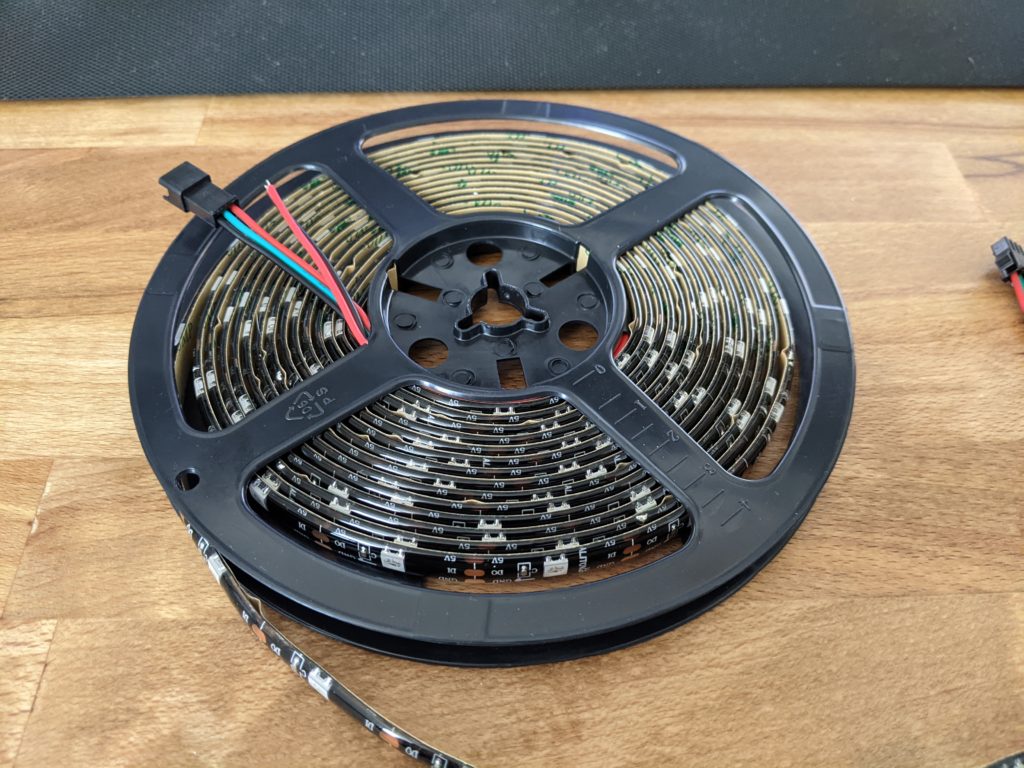
| WS2812B LED Strip | 16.4 feet of individually addressable RGB LEDs. 150 LEDs per strip. | 16.4ft WS2812B Individually Addressable RGB LED Strip Light |
| USB Wall Charger | This USB port will output 5V and up to 2.5 Amps. | USB Wall Charger 2.5 Amp |
Flashing WLED to the ESP32
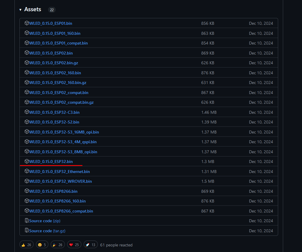
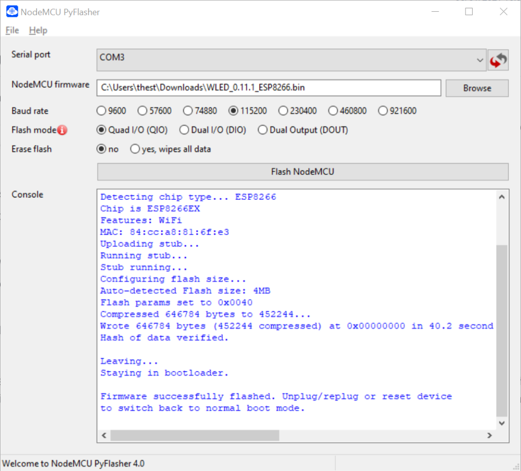
I downloaded the NodeMCU PyFlasher for windows. After getting the flash utility, you need to get the WLED firmware to flash to the ESP32. The firmware can be found in the list as just the plain ESP8266 firmware.
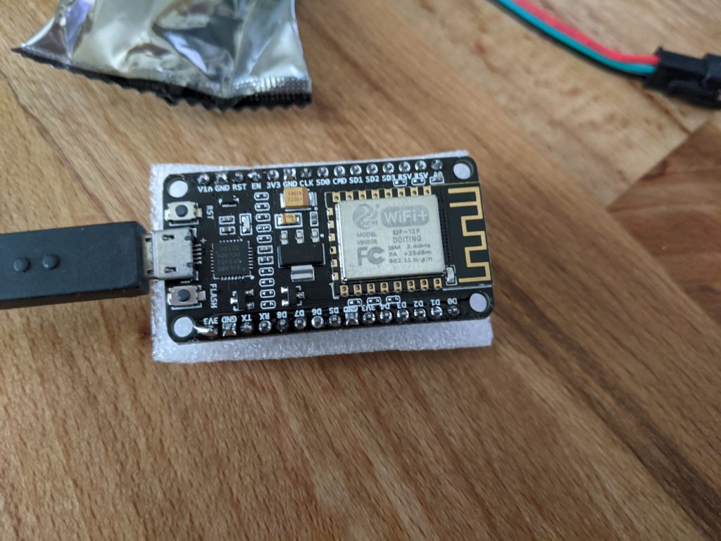
Plug in the ESP32 to a USB port on your machine, windows should install drivers to communicate with the device. Open the PyFlasher next, which, it should have the ESP in the list of available COM devices. I had to verify I was using the correct COM device by using device manager and expanding the “Ports (COM & LPT) and finding the COM port for the unit.
Set all of the options in the NodeMCU PyFlasher, selecting the COM port for the ESP32, browsing to the firmware file downloaded from GitHub, and leaving most of the other settings as defaults (settings shown below).
The guide I was following used used all the default options in the flashing utility, so I tried that baseline for my first attempt, however this didn’t work. I needed to adjust the flash mode from Dual I/O (DIO) to Quad I/O (QIO). Once all the settings are made, click the “Flash NodeMCU” button and wait for the success message.
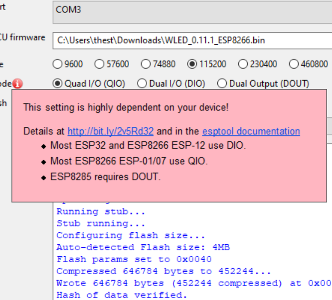
I determined that the Flash mode was the setting to update by looking at the info block for the flash mode. The info block mentioned that some of the units used QIO, so I tried using that setting and the flash was successful.
Wiring Up
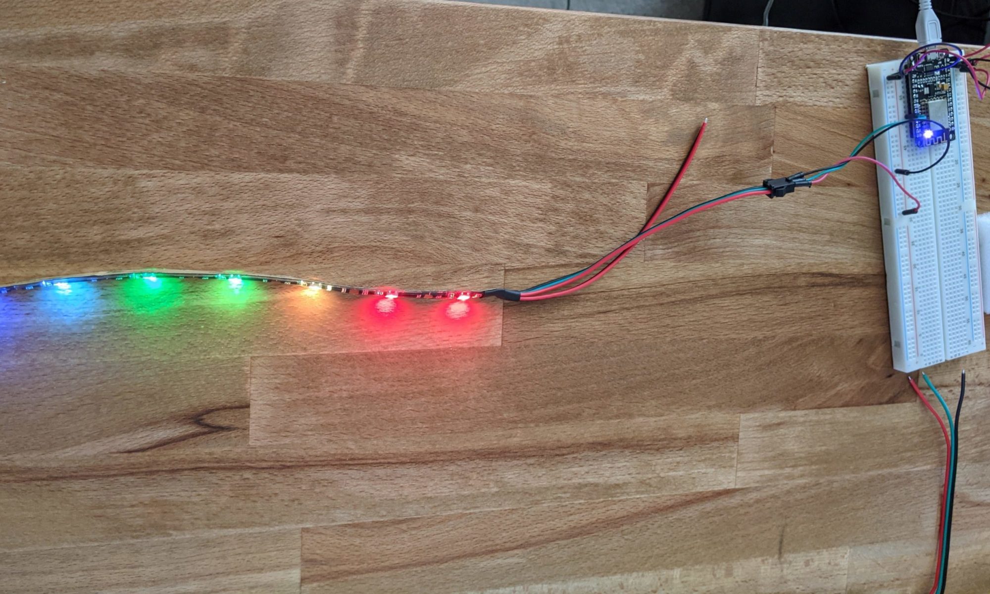
I did not use an external power supply for my LEDs for this. This does limit the number of LEDs that can be driven, however it does allow us to hook it up quickly to test out the newly flashed firmware and the LED strip.
Before wiring the ESP32, disconnect power and make sure to wear a grounding strap. The wires can either be soldered onto the unit directly, or can be hooked up with a breadboard, or any other way.
| Wire Color | Summary | Pin |
|---|---|---|
| Red | 5V Power | Vin |
| Black | Ground | GND |
| Green | Digital out. | D4 |
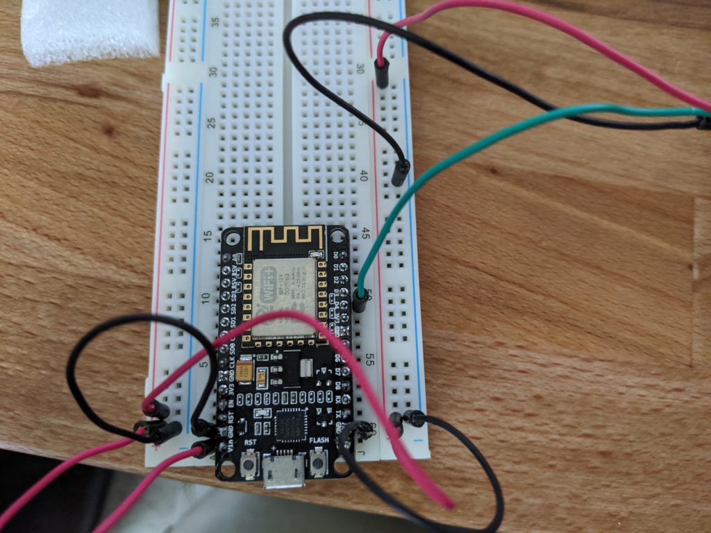
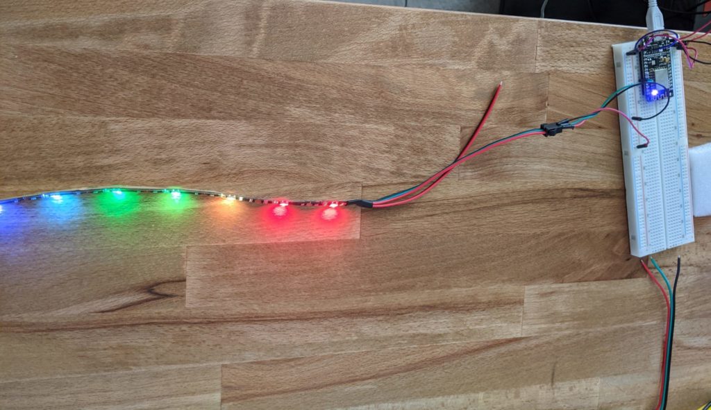
While unnecessary, I hooked up the VIN and GND pins to the breadboard + and – lanes and hooked my LED strip up there, I could have simplified the entire thing by just hooking up directly.
Starting Up
Once everything was wired up, I plugged the ESP into my USB charger and it turned on. I noticed that very few of the LEDs in the strip were turned on, and in the settings I found that it had defaulted to running 30 LEDs. This is fine since I’m not sure what the power limits are that I can draw through the pins on the ESP before I need to use the external power.
WLED Settings
The ESP32 will create a WiFi network that can be used for initial setup and for controlling it. Connect to the WLED network using the following credentials:
- Password: wled1234
- SSID: WLED-AP
Once connected to the access point, you should be greeted with a captive portal. You have the option to configure the ESP32 to connect to your local WiFi or you can just start controlling the LEDs. I would suggest connecting the controller to your WiFi network (leaving the built in AP on until you confirm its connected successfully. Afterwards go to the webui and start playing with the settings.
I setup the ESP32 to connect to my IOT network and turned off the local AP once I saw the device in my Unifi dashboard. While I don’t have the entire project laid out yet for what I’ll be using the light strip for, I now have everything hooked up and setup and ready to be used.
Resources
Some of the links in this post are affiliate links, which means I may earn a small commission if you make a purchase through them—at no extra cost to you. This helps support the blog and allows me to continue creating content that you love. I will only recommend products and services that I trust and believe will be beneficial to my readers. Thank you for your support!