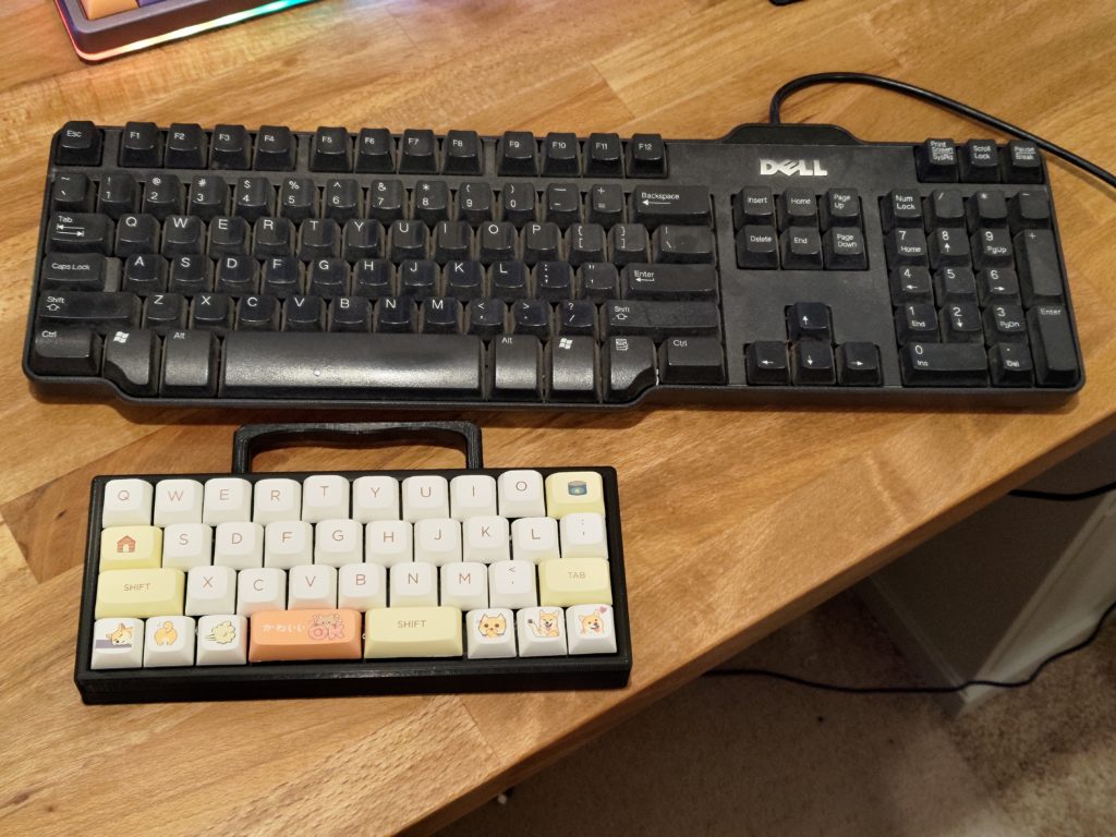
I saw a cute keyboard online at one point, an absurdly small keyboard, 35%. I decided to build one myself, there’s a kit available with the circuit board and diodes, just add switches, micro controller, and case. I did end up complicating things a bit though, adding hot swap sockets and I plan on eventually adding a plate as well.
I started with picking up all the parts needed for the QAZ keyboard. This is a small 40% keyboard kit you can get, the circuit board comes with diodes and has a version that comes with the needed pro micro as well. I did want to make the switches on the keyboard hot swap, so I did some research to find some good hot swap sockets to use as well.
Parts
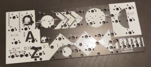
- Circuit board
- Case
- Switches (Cherry MX Blue)
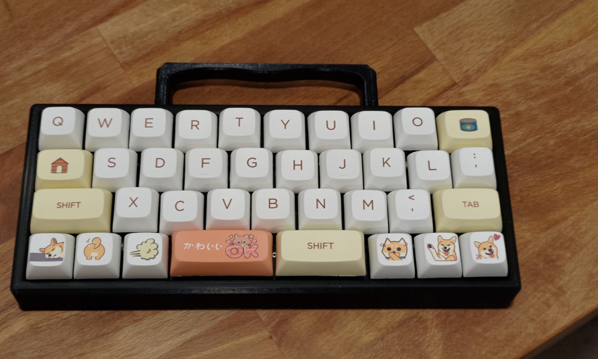
- Keycaps (CORGIS!)
- MillMax Hot swap sockets
- Pro micro
- Plate
Hot Swap Key Switches
While digging around looking for hot swap sockets for my keyboard build, I found two main types. The first type are the surface mount type sockets that won’t work for my build as the pads on the circuit board aren’t positioned for them.
The second type I found are MillMax sockets that mount in the through holes and grip the pins from the key switches there. They do have some limitations on switch type they support (limited by the pin size on the switch itself), but they will fit my circuit board and give me the best feature, hot swap switches. When pricing out how many you need, just remember you need two per switch, and these are SMALL, so make sure to get some extras too. I picked up a pack of 100.
Assembly
Starting out with the assembly, we have to start with the soldering where we have a few things to add to the board:
- Diodes
- Hot Swap Sockets
- Controller
We do have to solder in that order too, we can’t add the controller till after everything else is done.
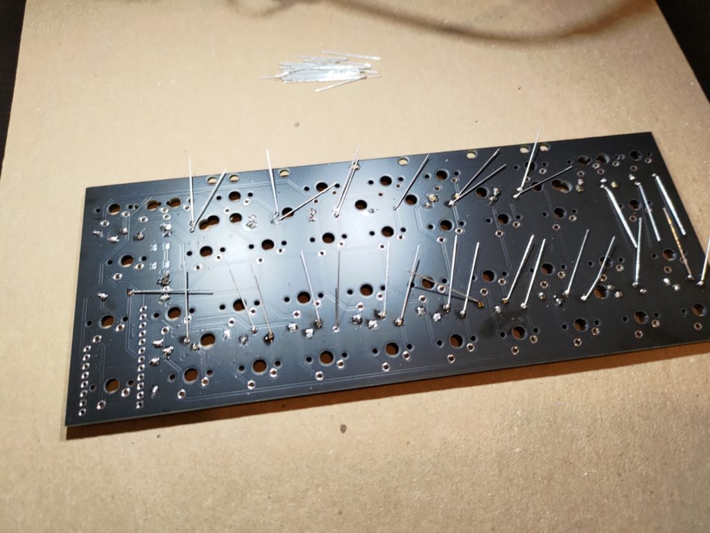
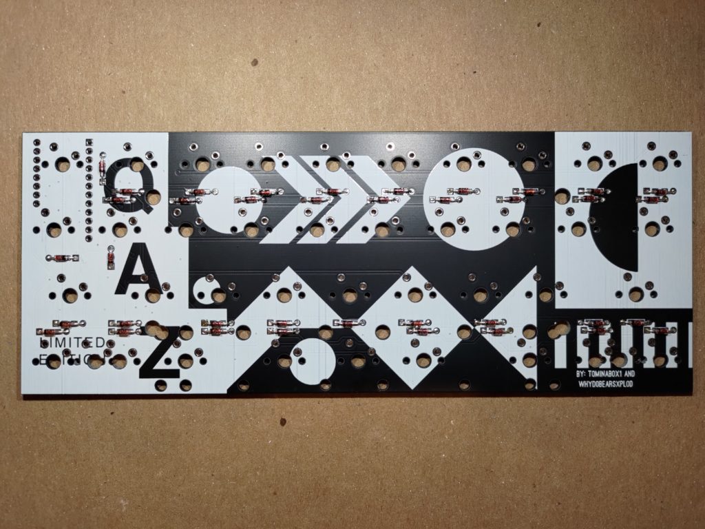
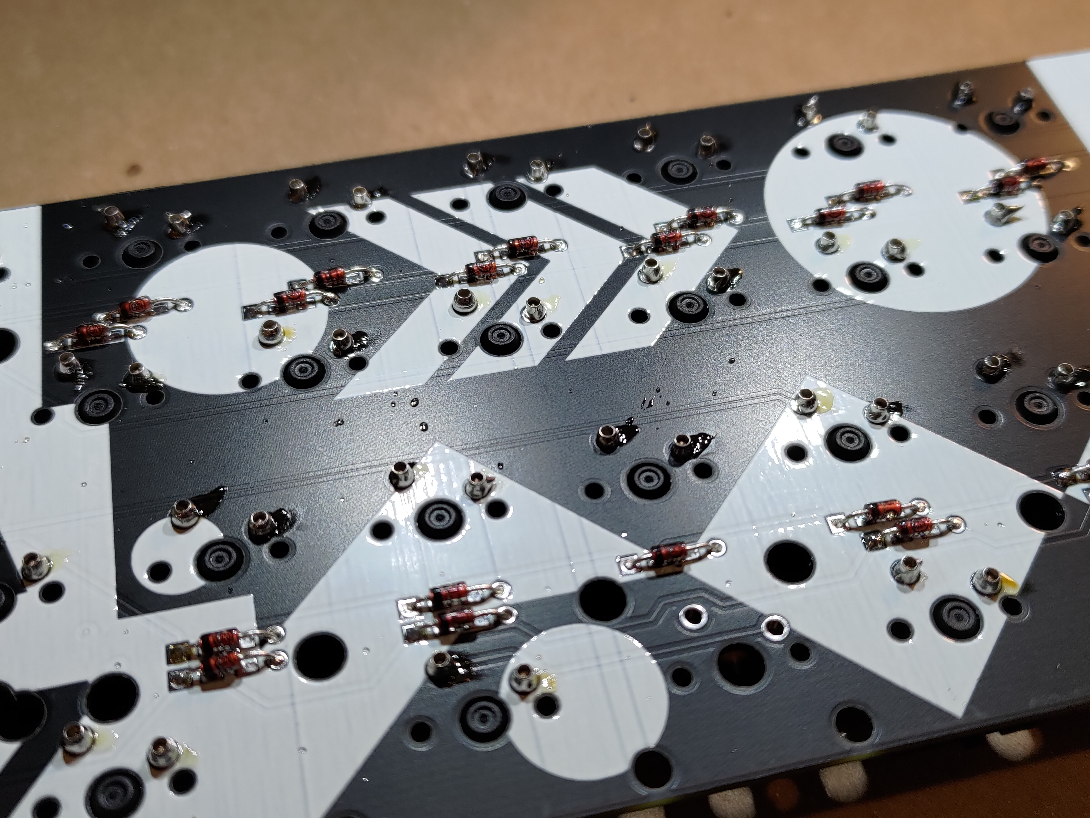
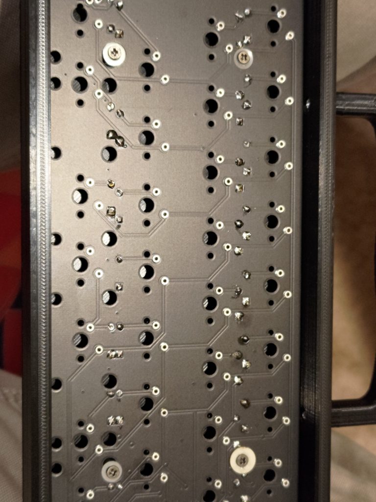
I started out by soldering in all the diodes. After they were soldered in, I trimmed off the tails and went on to the hot swap sockets.

Next up are the hot swap sockets. I used the switches themselves to help hold in the sockets during soldering.
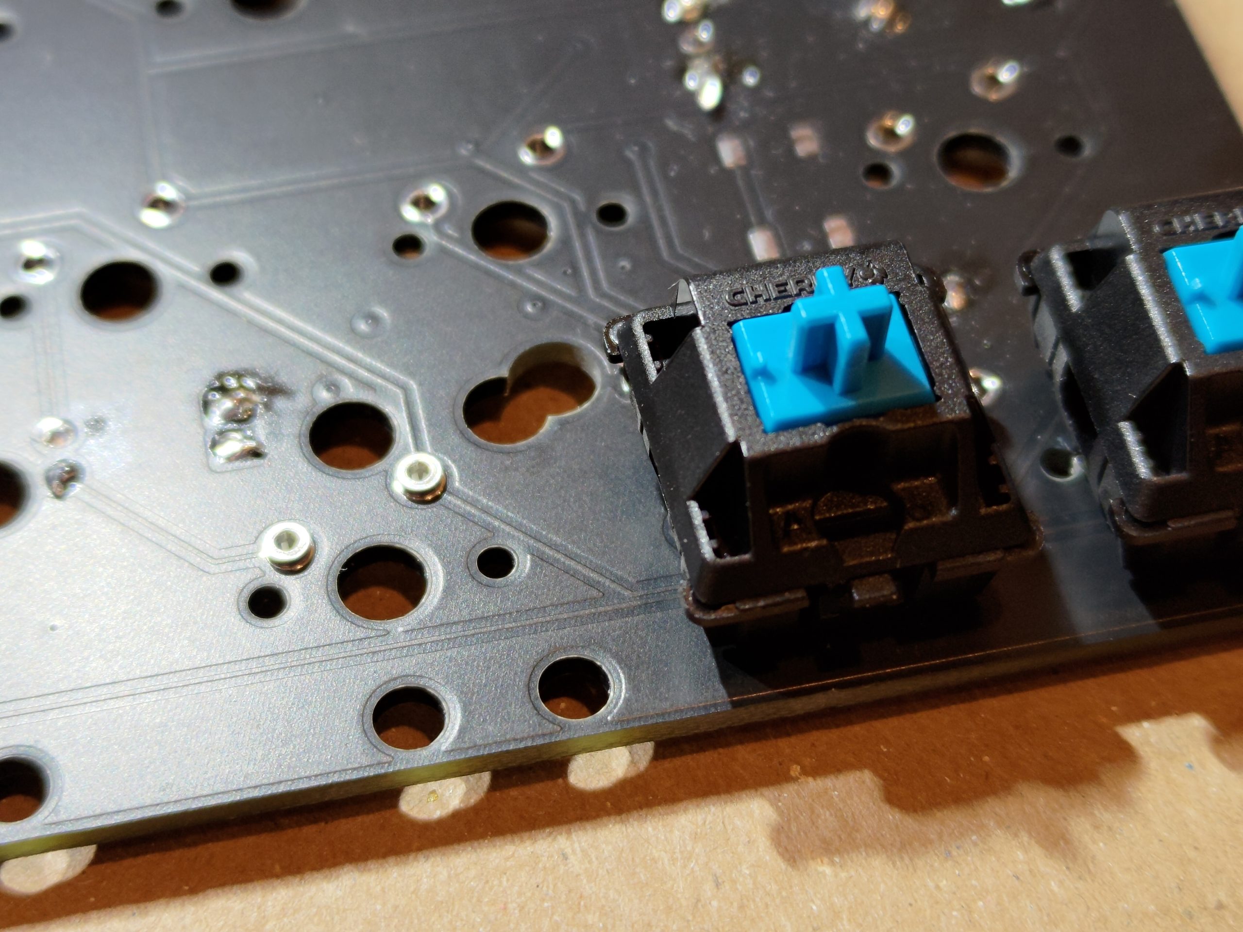
Solder the hot swap sockets carefully. You don’t want to flood the interior of them with solder or else it’ll no longer be hot swap. I heated up one side of the socket and applied solder directly to the base and didn’t have any problems, though I did come close to flooding one, but I didn’t fill it enough to solder in the switch or keep it from working.

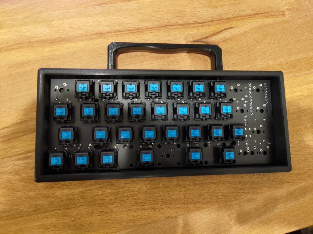
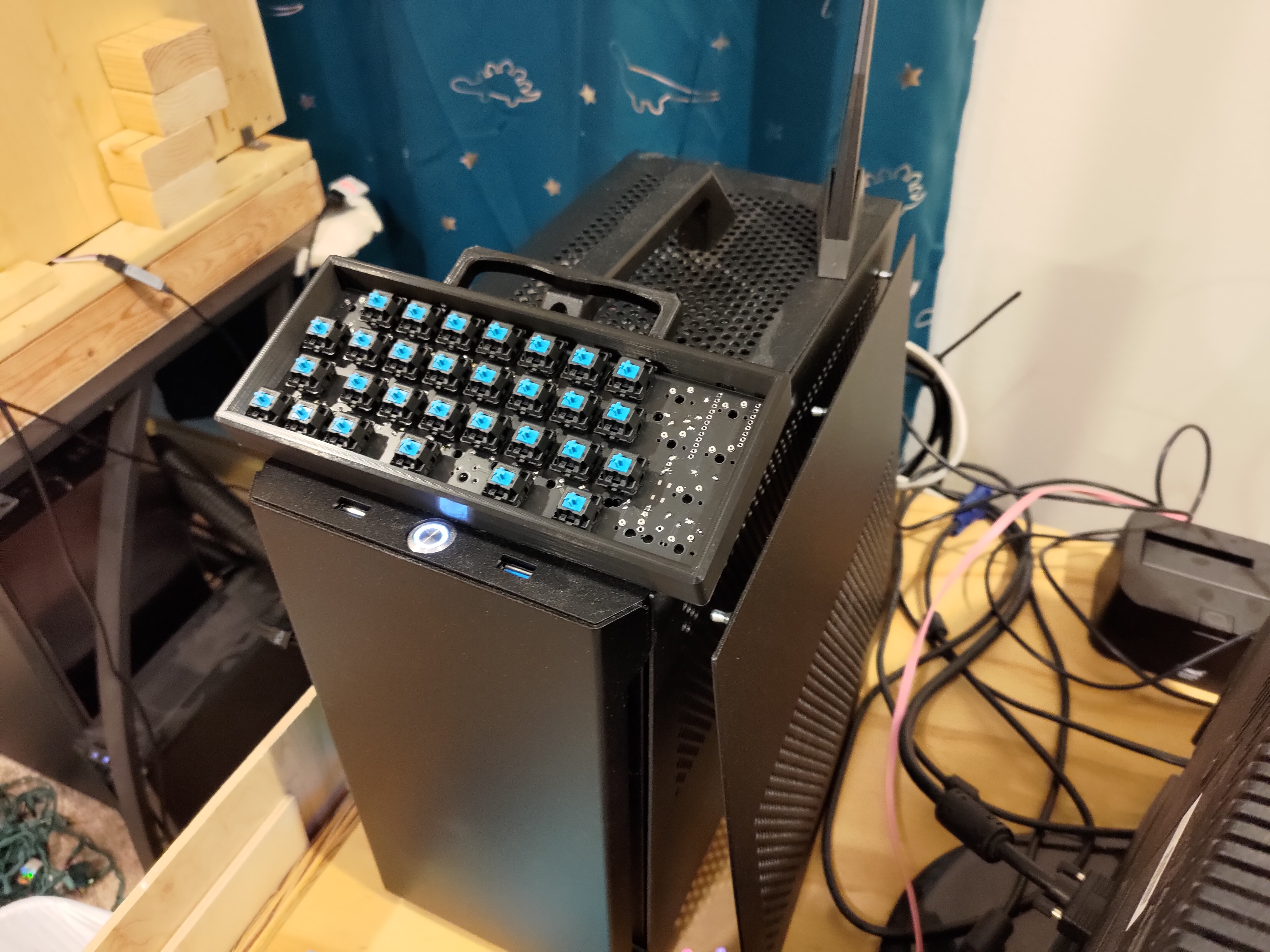
After getting the switches in, I dry fit it into the case and took a few photos because one can never take too many pictures.
I picked up a pro micro for the keyboard with the headers already soldered on. This ended up being a bad idea as the headers needed to be soldered into the other side for the circuit board layout to work.
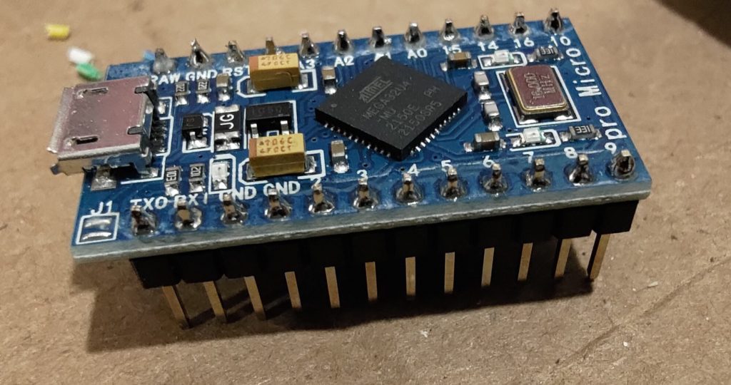
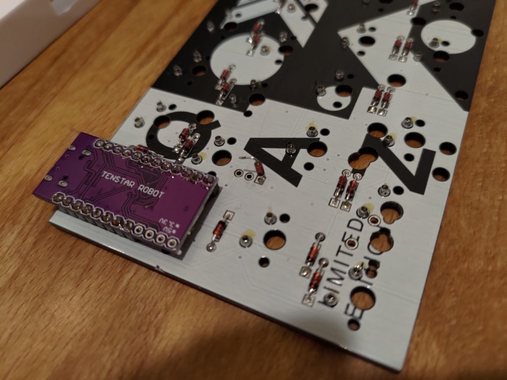
As I’m lazy at times, I picked up another pro micro without headers and this time did it the right way. I started by cutting off 4 pins from one of the headers.

Afterwards they were soldered onto the pro micro, and then the pro micro assembly soldered to the main keyboard circuit board.
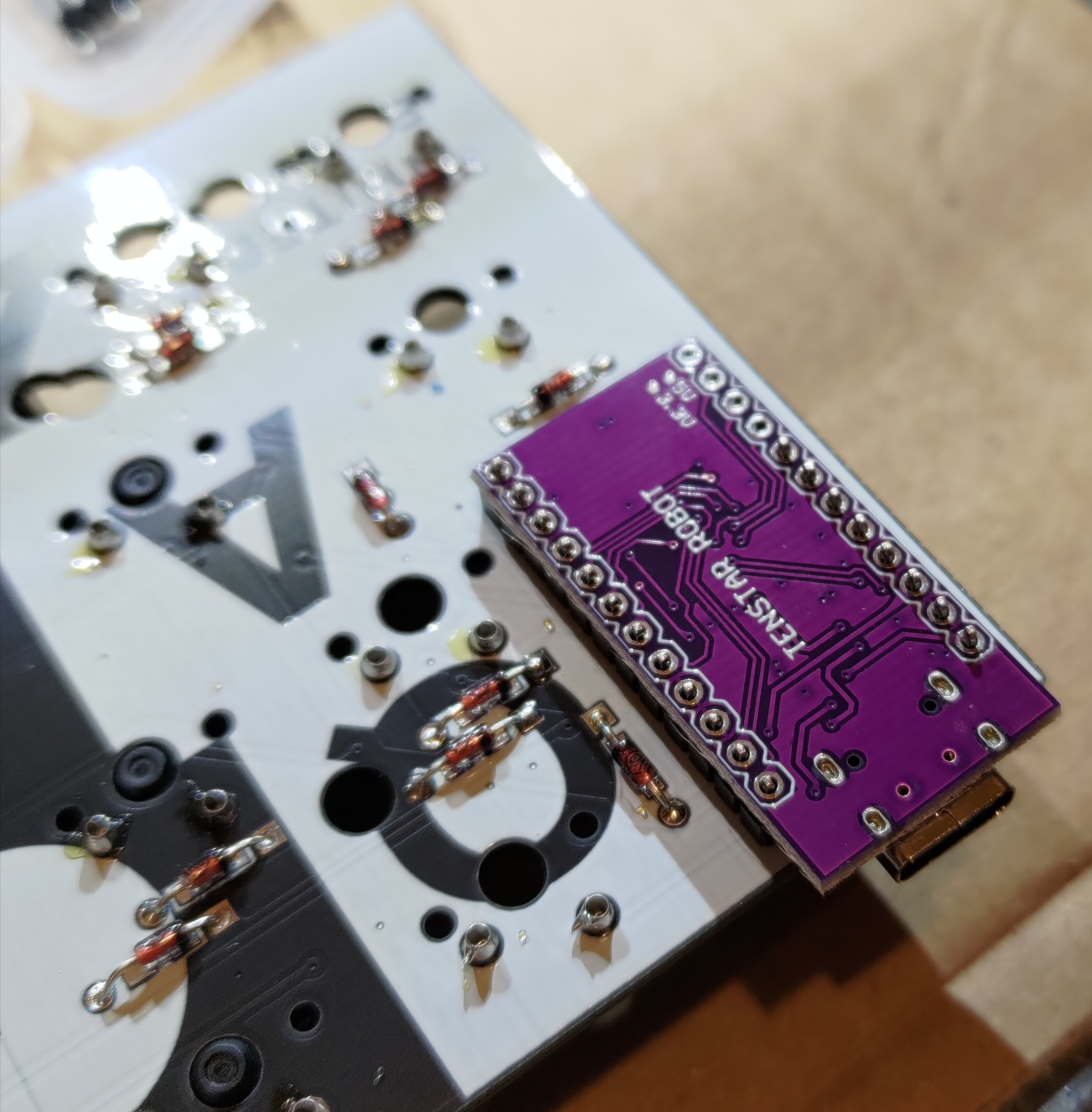
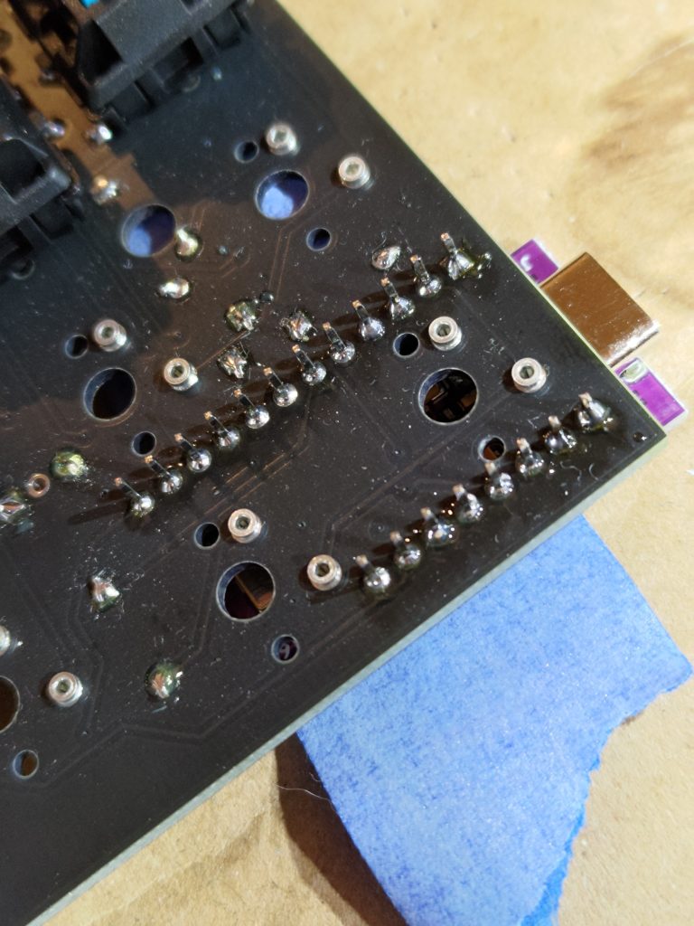
Now we start running into problems, from the top, we can see the pins pushing through the board, these protrude more than allowable, as they’re running into the switches in that area. I used a side cutter and trimmed the pins close to the board to get rid of the interference.
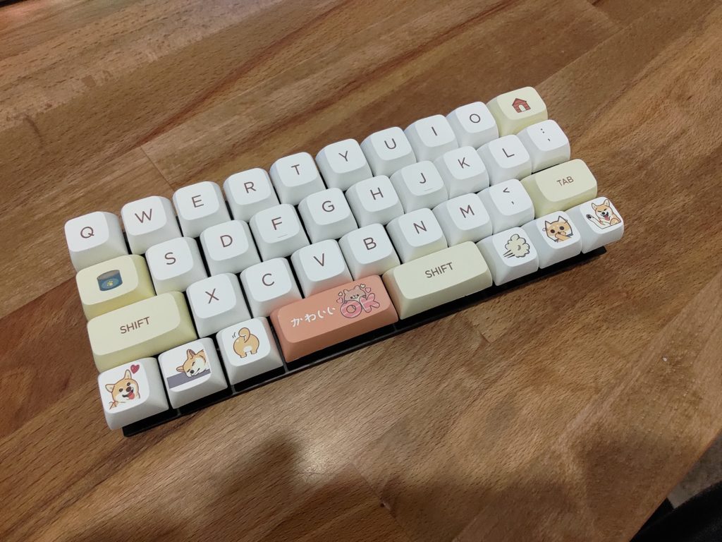
With that out of the way, I plugged in all the switches and added keycaps. It might still be early to do this but I wanted to see it in all it’s future beauty.
More Problems!
Since no electronics project can be done without any problems, not even a simple circuit like a keyboard, we’ve run into some. When I plugged in the soldered keyboard, the controller started heating up and the PC didn’t register any new devices as connected. Not good.
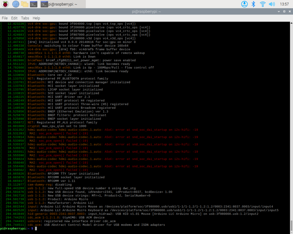
I started by desoldering the controller from the board and testing it. The controller had some parts that were very close if not touching the switch sockets, so there may have been a short through that. I plugged it into my raspberry pi and ran dmesg to make sure the system still recognizes it.
Since it was recognized by the pi, it must still be functional. So I soldered it back onto the circuit board, this time with a bit more spacing and electrical tape to insulate it from the sockets.
This didn’t fix it, the controller still heats up when plugged in and doesn’t connect to the computer. Well now for more debugging! Since it’s a decent amount of heat being built up, my first assumption is that there is a short. So I used my multimeter to verify there is indeed a short to ground from VCC on the board.
I started looking for the source of the short and noticed an interesting detail that was printed into the early boards for this keyboard. A debug header.
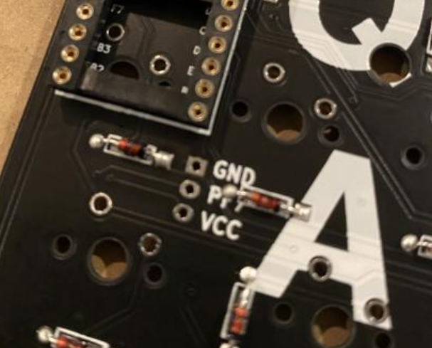
I noticed that I had soldered a diode into this port as it had all the markings that the other diode locations had. I de-soldered one half of the diode and pulled it up so it wouldn’t make contact. I then plugged the keyboard back into my pi and checked for the USB device to be detected. It was finally detected and so I finished de-soldering the diode and removed it.
Now that that’s out of the way, everything is looking good again. I can continue assembly of the board into the case and key switches and caps installed.
Final Assembly
Now that it’s working, I assembled it into the case, bolted it into place, and added switches and caps.
The fit isn’t perfect as I have some washers to hold the mounting screws in the right locations and they’re intersecting some of the switches, knocking things out of center in some places. I’ll return at another time to fix this up.
Flashing the Firmware
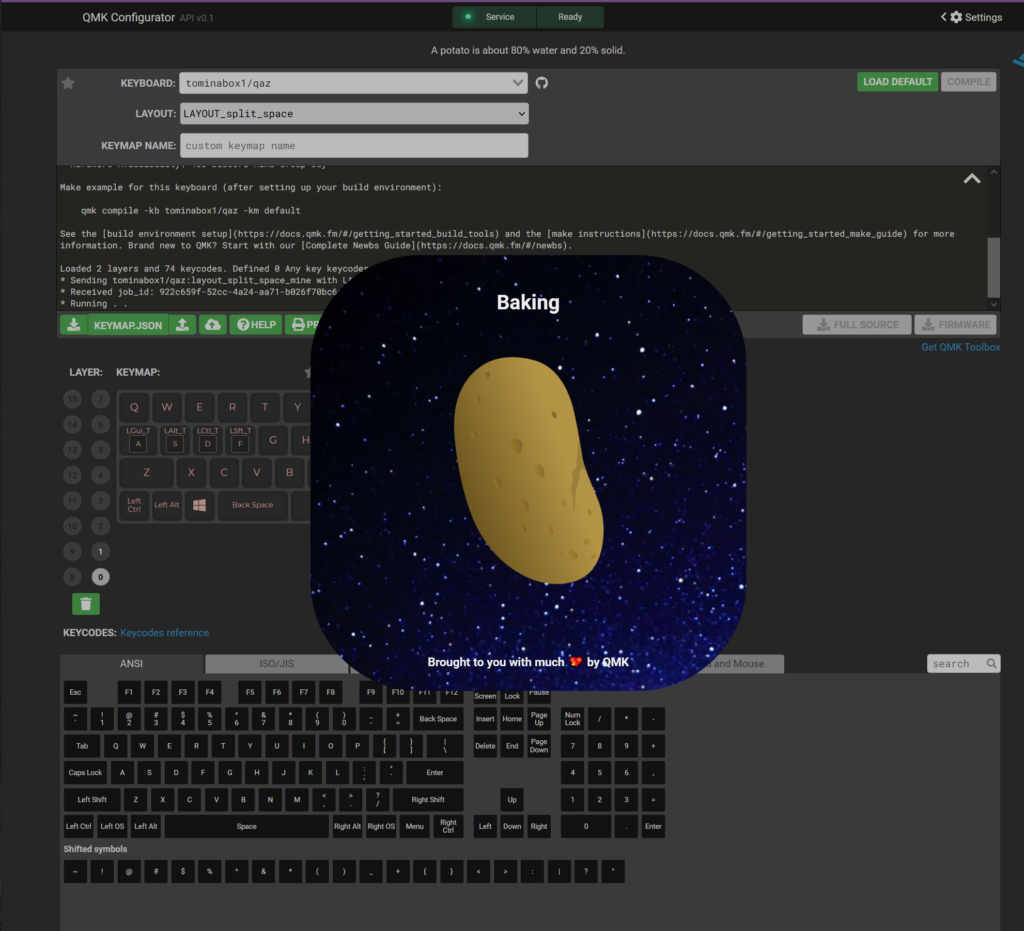
I went to the qmk site to generate the firmware, and they had a profile available for my keyboard already, no need for me to create one. I probably won’t keep it on the stock profile for long, but I can get it working faster this way.
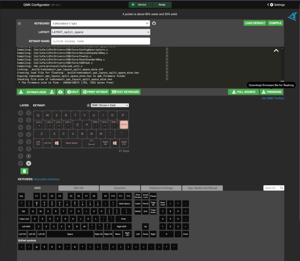
I used the site to build the firmware that I needed for the pro micro. This was all pretty straight forward which made me quite happy.
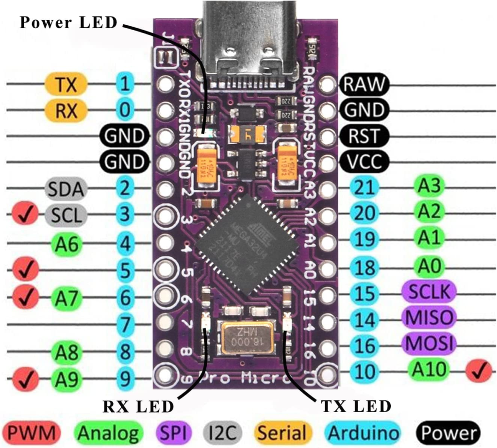
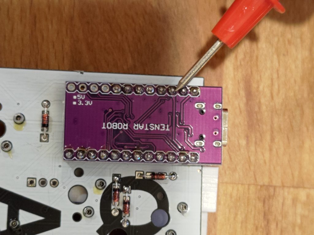
Now on to flashing our firmware. The board can be put into flashing mode with 2 quick shorts of the reset pin to ground. I grabbed the pin-out of my board and found those right next to each other, easy enough to short using a multi-meter probe.
On my PC I pulled up QMK toolbox and loaded the hex file for the keyboard. I also turned on auto flash mode for reasons mentioned later on. I plugged in my keyboard as well at this point.
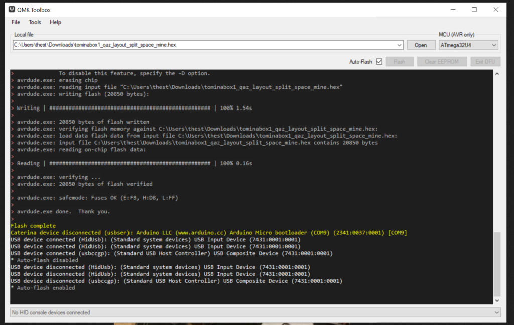
With all that ready, I double tapped reset and watched QMK toolbox do the rest.
I tried double tapping without auto-flash and never could get it to work. The board would be out of flashing mode before I could push the button on QMK toolbox to flash the firmware. So auto-flash for this first flash is a necessity.
Conclusions
The project was pretty fun to build and as a first custom built keyboard, I’m fairly happy with it. It does have some odd issues I’d like to work out to make it nicer to use, but those are from my own build and not a problem with the design itself.
This thing is going to be fun to try and come up with a good typing layout, or it may become a large macro board, we’ll see.