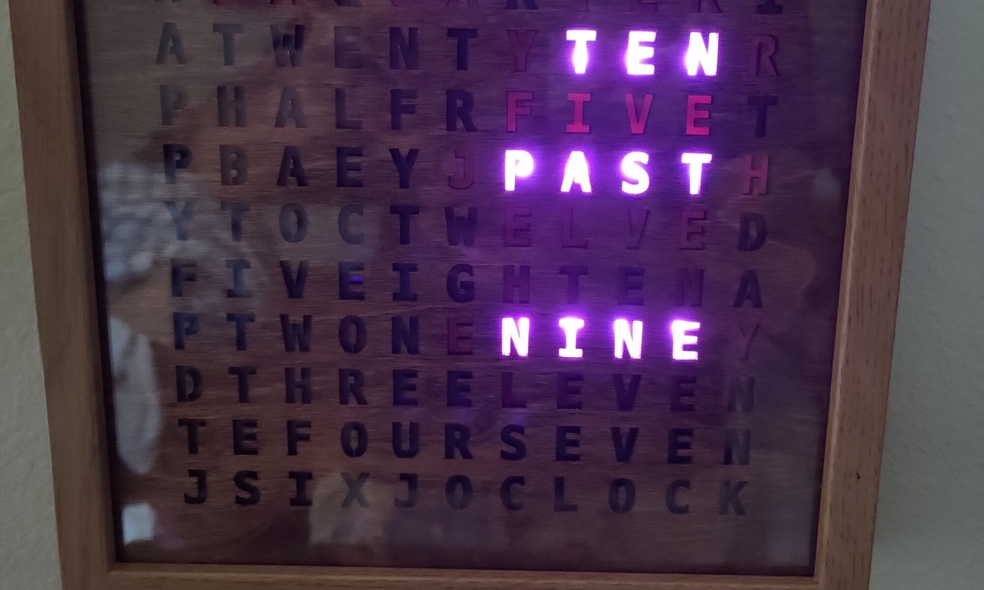
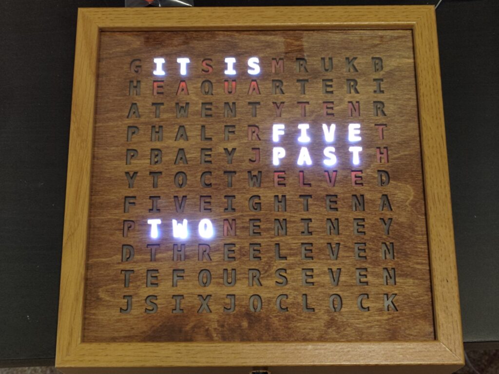
Way back around 2013, something started getting popular on Instructables, word clocks. They gave the time as a sentence instead of a usual number like most common clocks. I thought these were cool and wanted to build one, I even picked up parts, but never got around to building it.
Design 1
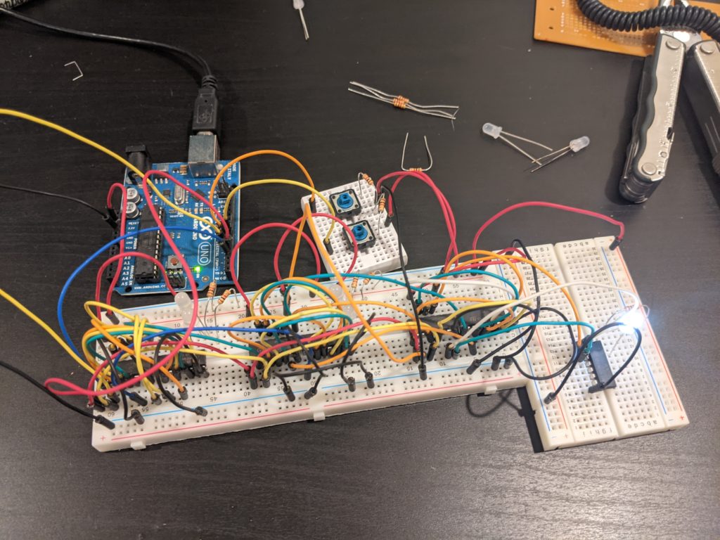
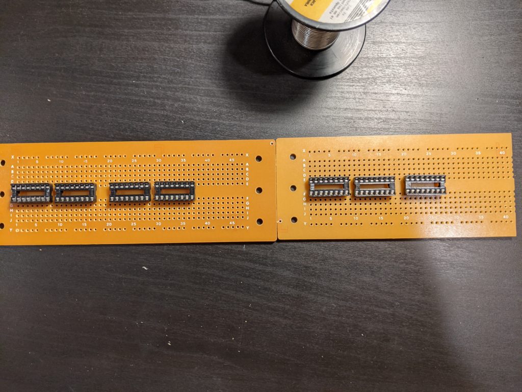
A year ago, I pulled all those parts out and started working on it again, I even wired up most of it to breadboards, though it didn’t fully work. I started assembling the proto boards when I set it down again. I did have worries about debugging the boards once I had assembled them due to how many connections were needed in the circuit. This leads us to design 1.
After doing some (but not much) soldering past this, the project was set aside yet another time. This project that I picked up parts for over 7 years ago just simply never wants to be finished. But now in the current hiatus, I found another design for it. This new design is simpler, much simpler, SIGNIFICANTLY simpler. It no longer requires me to have multiple circuit boards worth of ICs to build, and stacks of connections that if I miss, break the entire system. This new method uses addressable RGB LEDs, like the kind you run with WLED, and a few off the shelf parts alongside the microcontroller to run.
Design 2
This design still has a decently sized parts list, but it’s nothing like the previous designs I’ve worked towards. Below is my final parts list, however I did assemble one of the circuit boards following the original instructions rather than my modifications.
Parts:
- 3/8″ heatshrink
- 1.5mm or 1/16″ plywood
- 3mm plywood
- Resistors
- 1 x 330 ohm
- 1 x 1K ohm
- 1 x 2k ohm
- 2 x 10k ohm
- 100 uF, 50v Capacitor
- Esp32
- Circuit board
- GL5516 Photo resistory
- DS3231 RTC (not totally necessary, but may be useful in the future)
- Power jack
- WS2812B LED Strip, 60 LEDs/Meter (about 16.5mm center to center)
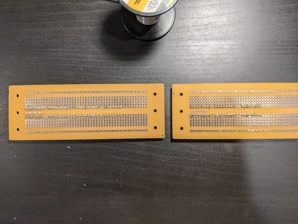
I started out by ordering the circuit boards online. JLCPCB has a minimum order quantity but with a board this size, it was still pretty cheap to get made.
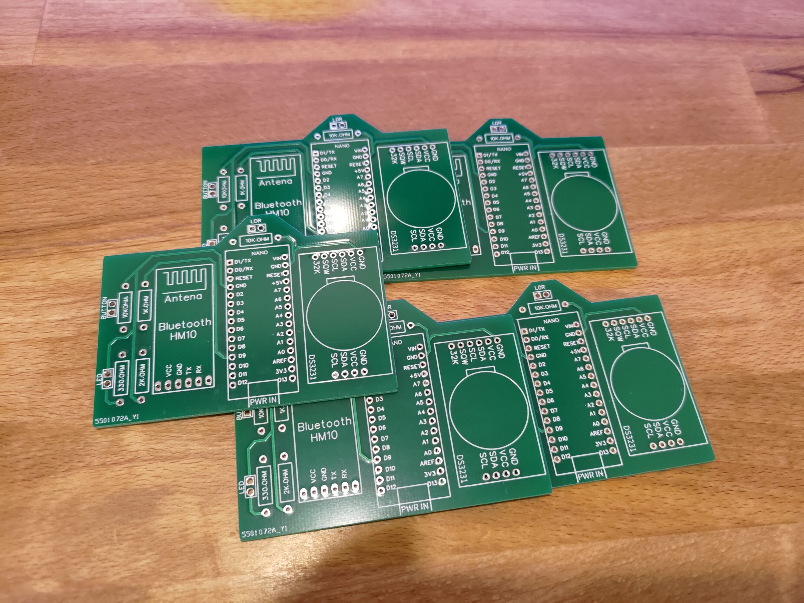
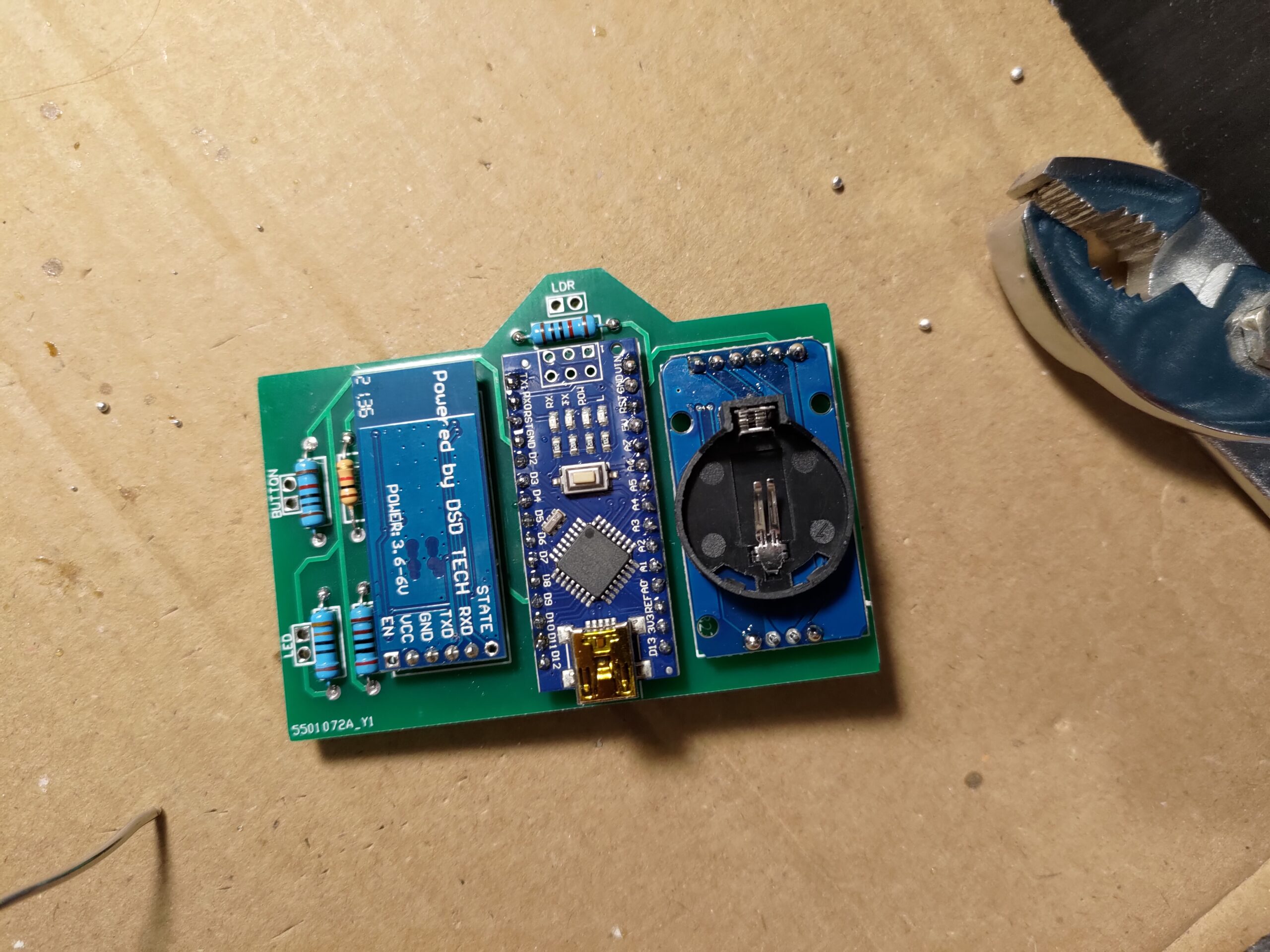
After I got the PCBs made, I quickly soldered up one of them with the necessary components from the un-altered design. Everything is marked out on the board as to what goes where so it’s a pretty simple build . I did solder on connectors to go to the LED strip and the light sensor. I wanted to be able to swap out the board if I wanted to go to an ESP microcontroller in the future, which I did end up doing.
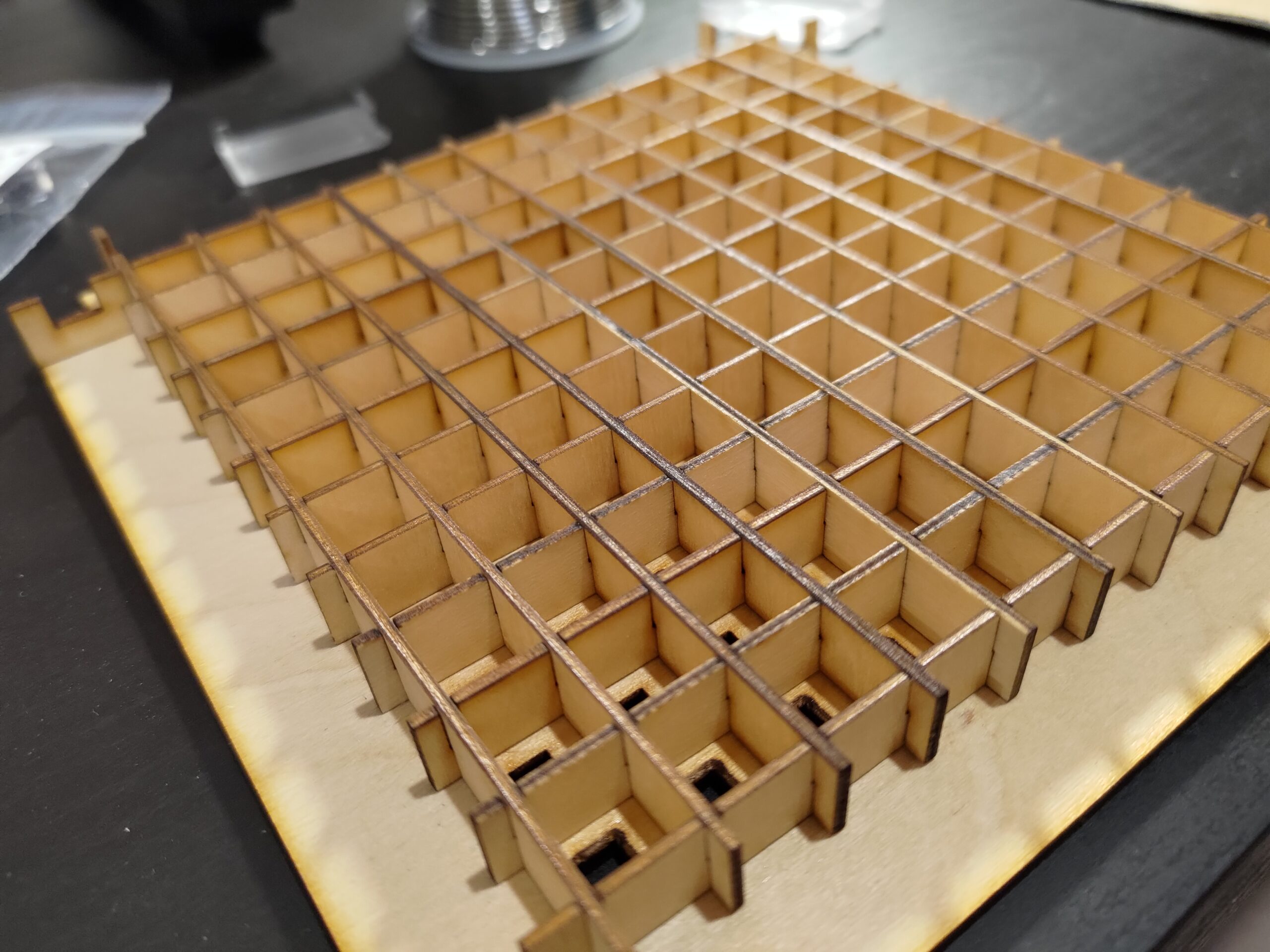
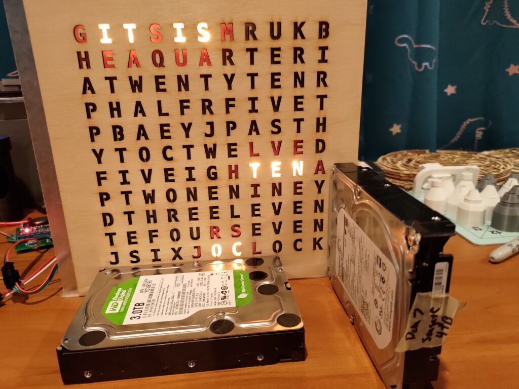
Now that the control board is ready, I started working on the face plate of the clock. The face plate has quite a few pieces in order to guide the light and provide all the characters.
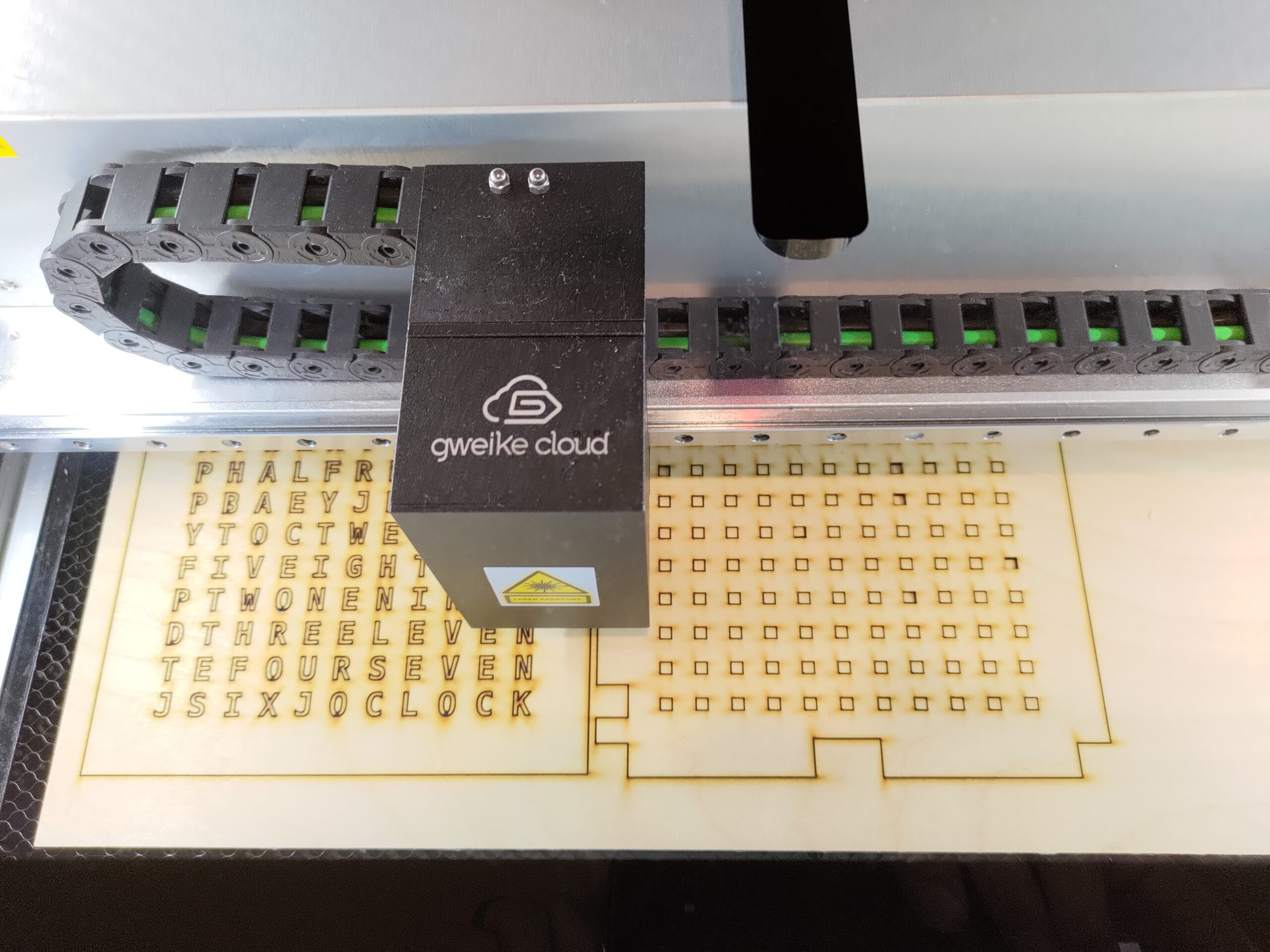
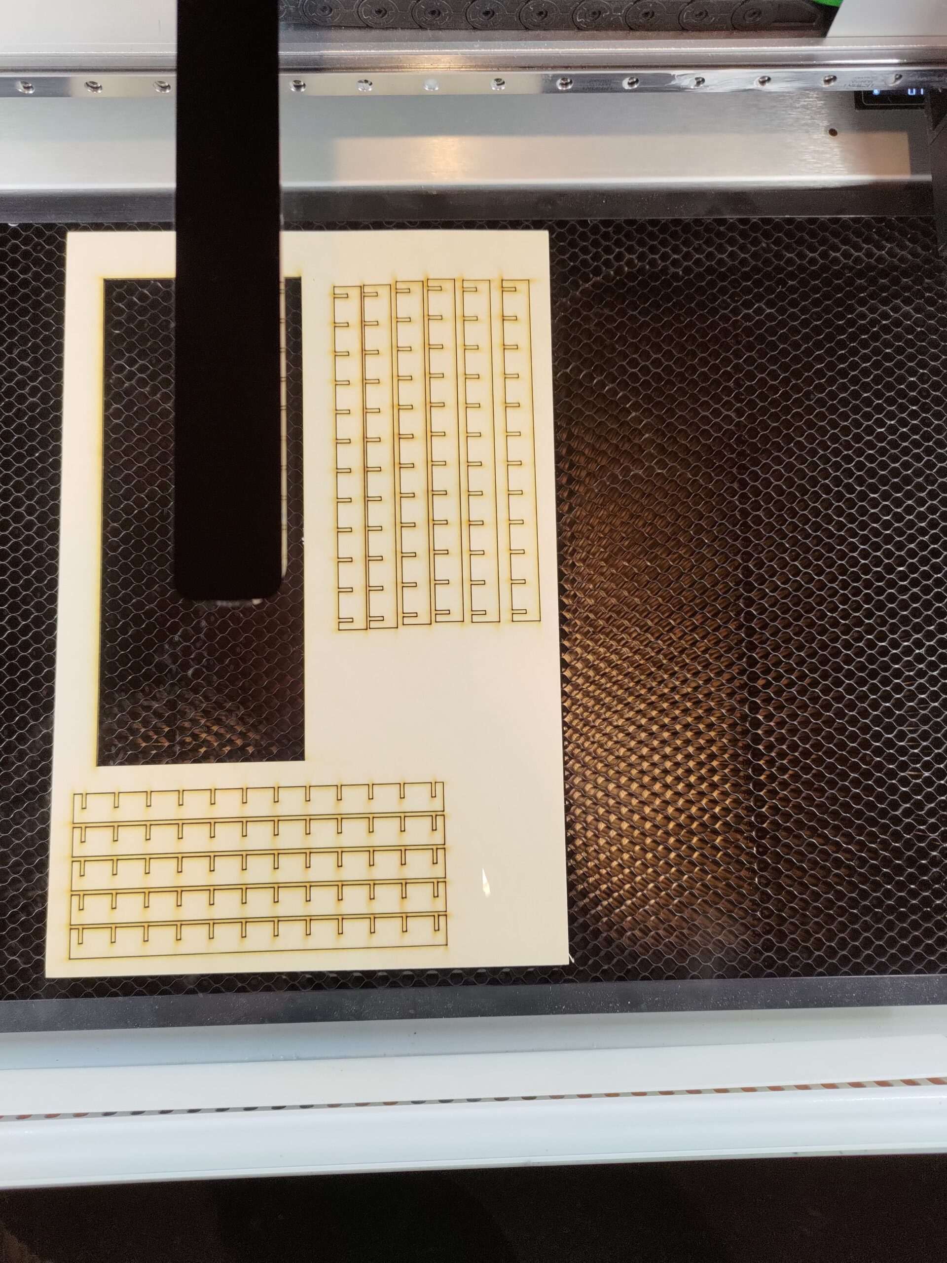
There are 3 different parts that make up the divider assembly. There are 2 different outer border pieces, and the inner pieces. The borders assemble to provide a wiring pass-through around the outside of the dividers.
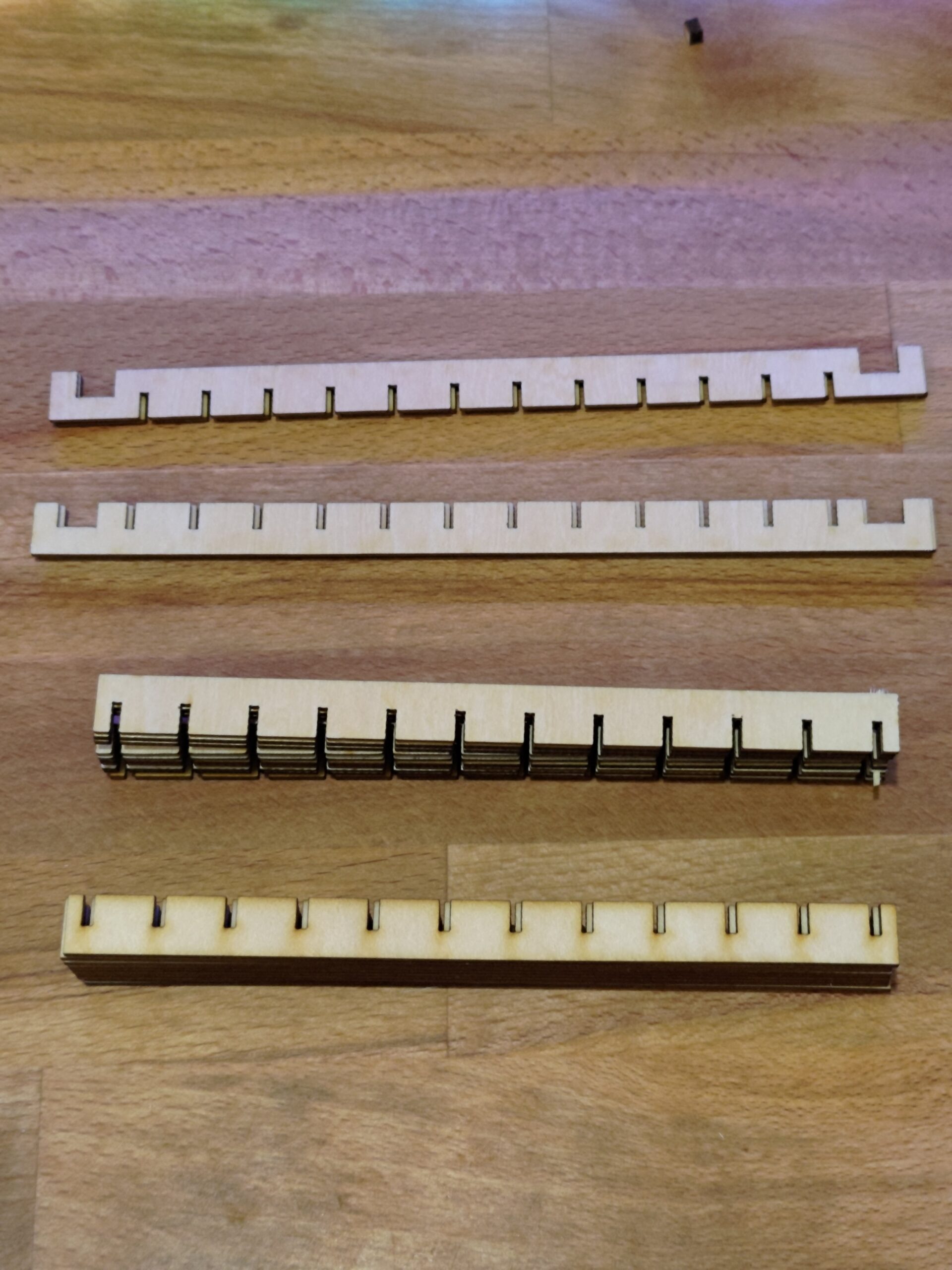
I glued the dividers together around the outside of the border and made sure they stayed at least mostly square while drying.
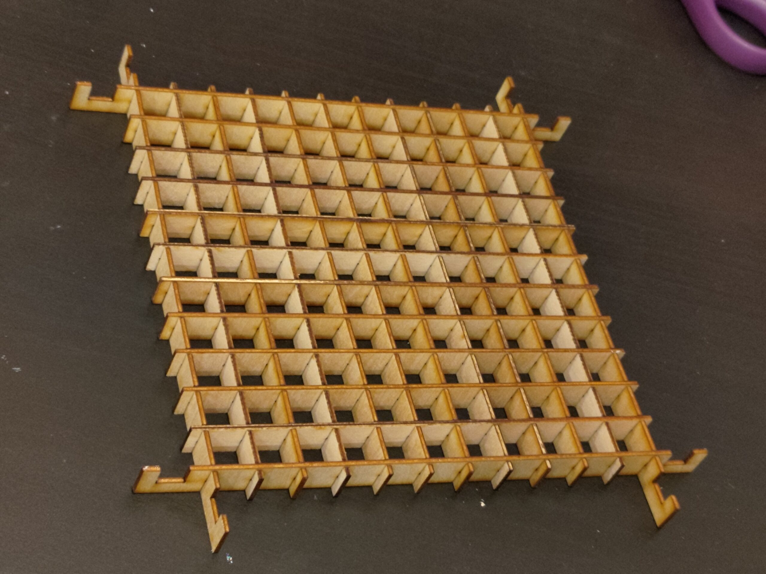
It was then that I realized that something didn’t quite add up.
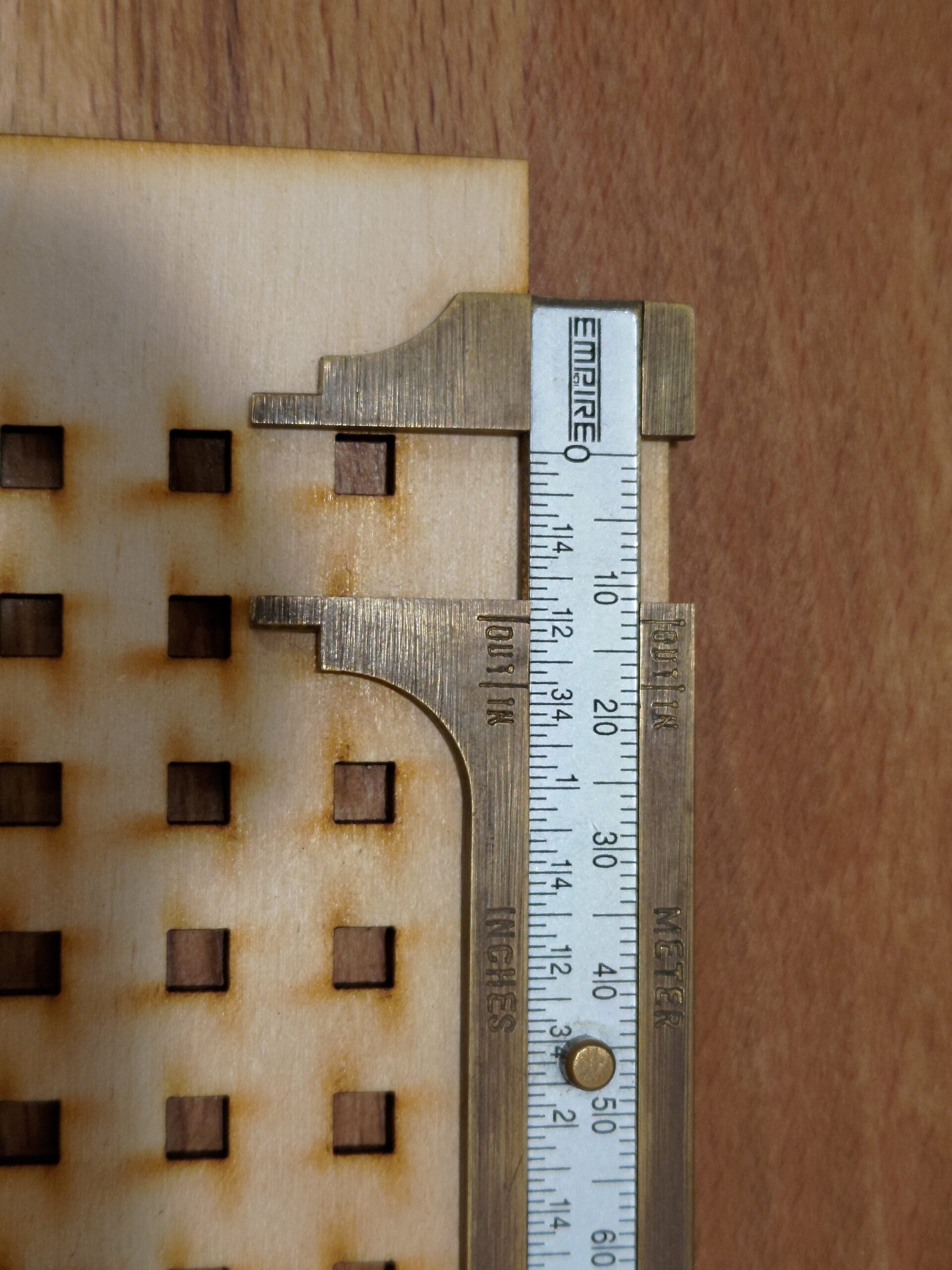
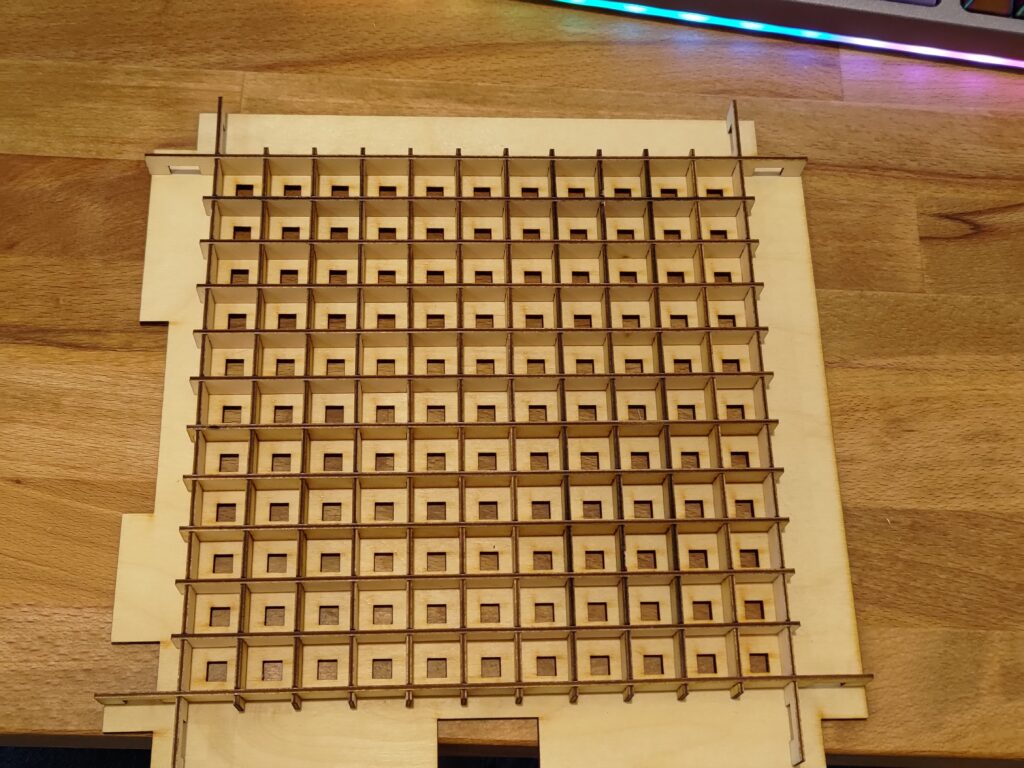
The dividers don’t match the spacing called out for in the BOM and at other points in the design. This is made all the more confusing since the dividers are called out for a 1.5mm thickness and the slots for it all to get assembled together match that. This means that the design is intended at that size and not just some scaling factor off. The laser designs and the rest of the design don’t match, or there were two designs at some point and the wrong one was uploaded to github.
Well since all the models are the wrong size in the repo, it’s time to rebuild things. Starting with the word plate and LED plate, those can just be scaled up to the 230x230mm size. Taking some measurements in InkScape shows the LED spacing to be correct at that size without any additional modifications.
Next up is the dividers. These need a full redesign since the slots need to be sized correctly for the material, so simply scaling them up won’t work (side note, this is even weirder since all the laser cut files were designed for this size in particular). Using some Catia, I was able to rebuild the models. I imported the SVG files and modified them from there to have the correct LED spacing. The main catch I encountered was to include the material thickness of the slots in my LED spacing dimensions. Once I had it all redesigned, I was able to laser cut them out and assemble it a second time, this time it all lined up nicely.
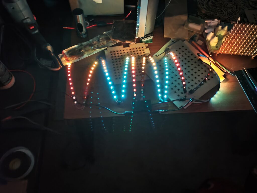
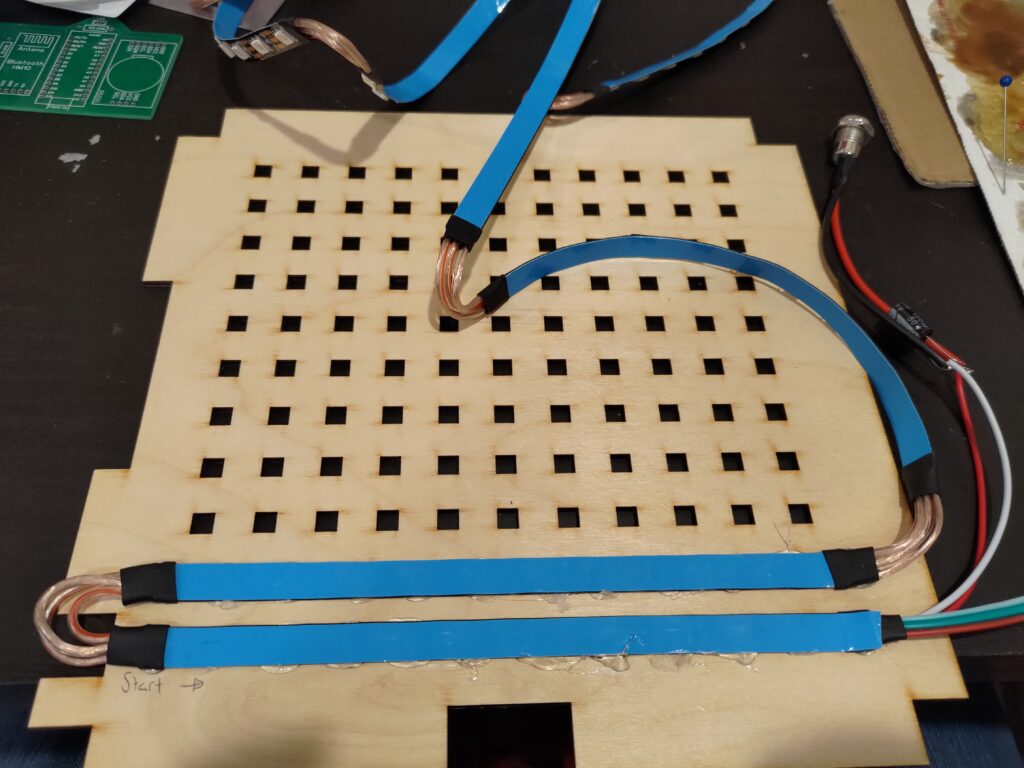
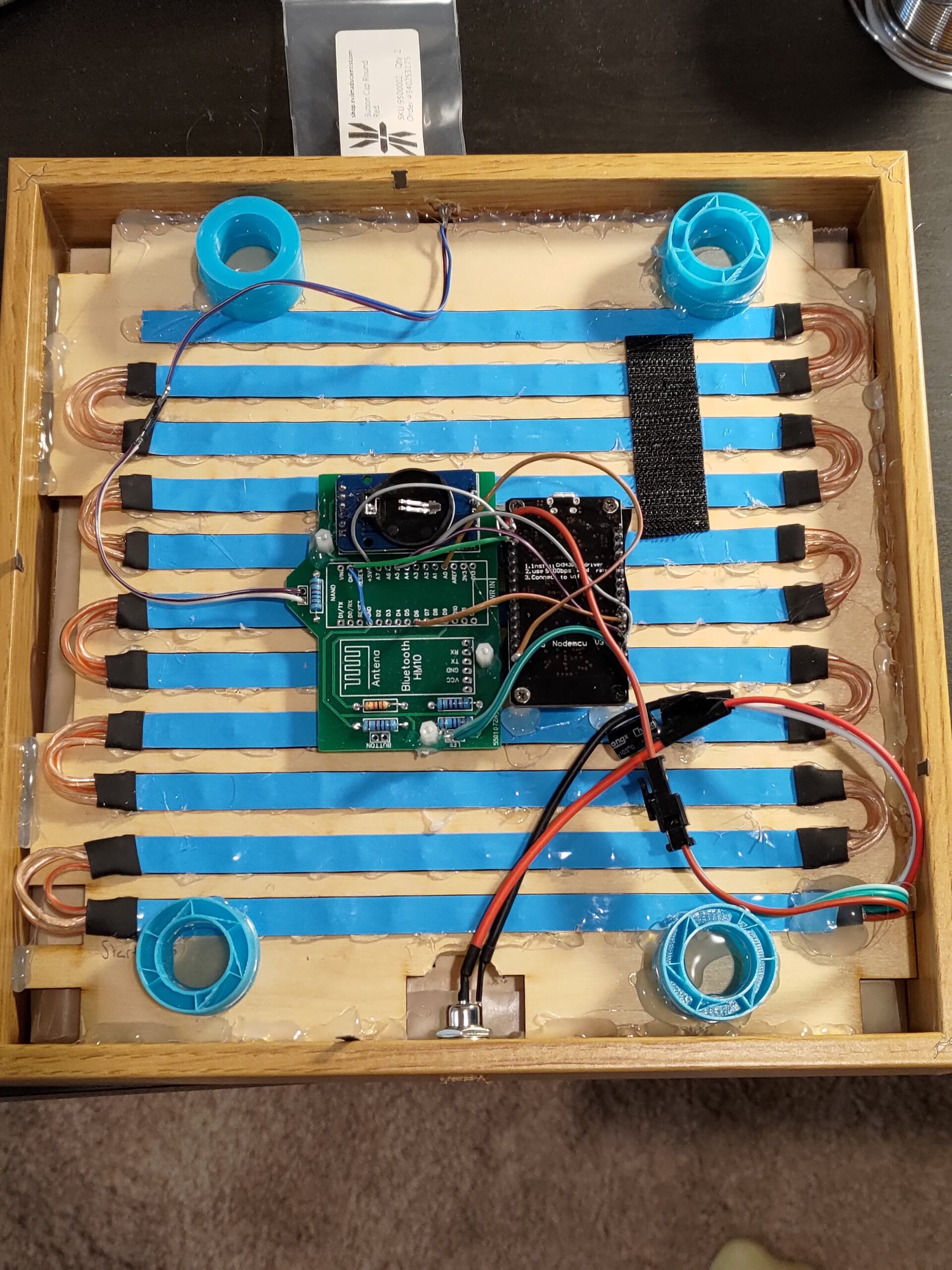
I taped the two led strips next to each other with about a blue tape rolls width from outer edge to outer edge. I then eyed up some lengths of wire, tinned the wire and LED strips, and soldered them all together.
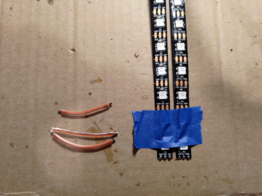
I then slid some pieces of 3/8″ heatshrink down the line so I had some for every joint in the LED strips.
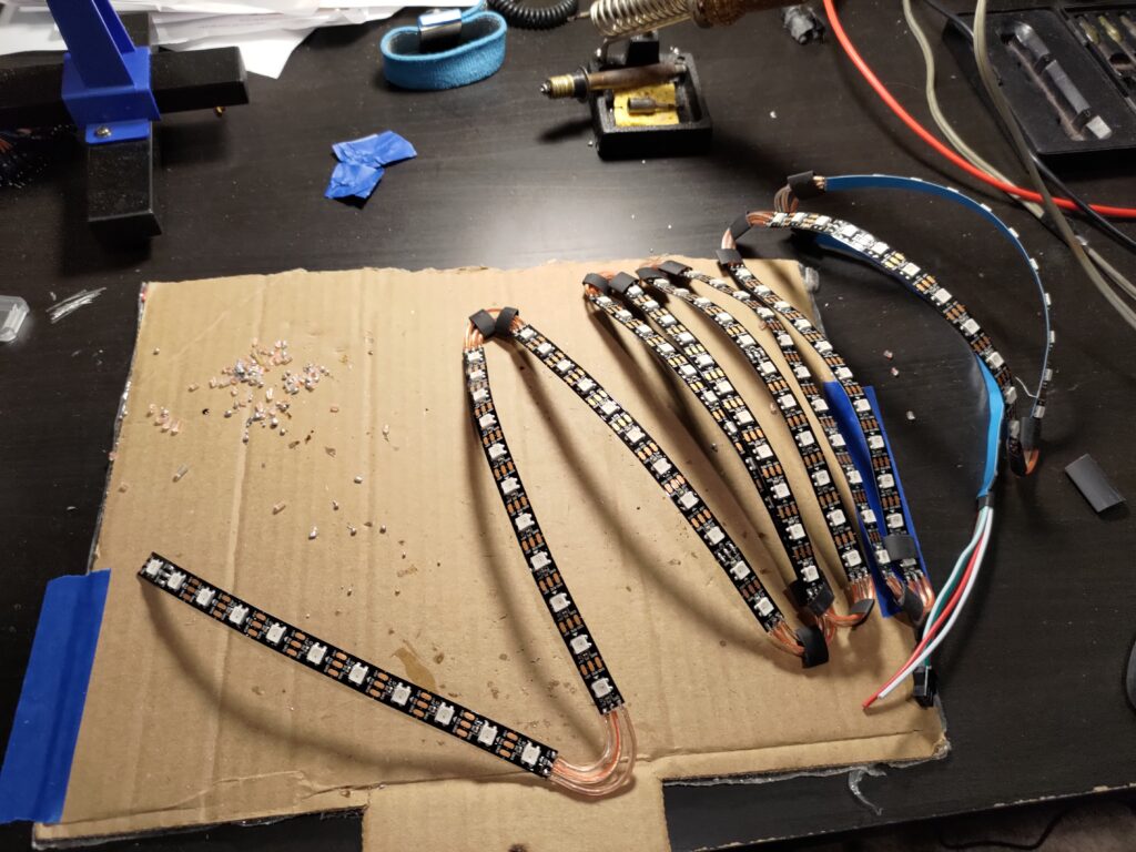
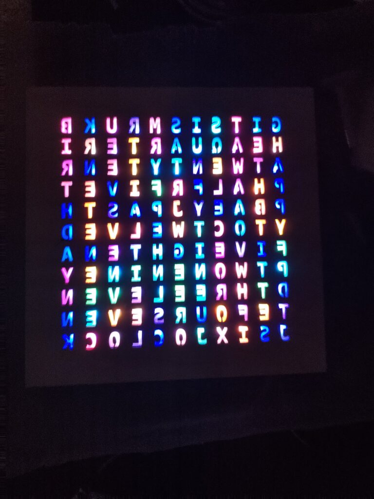
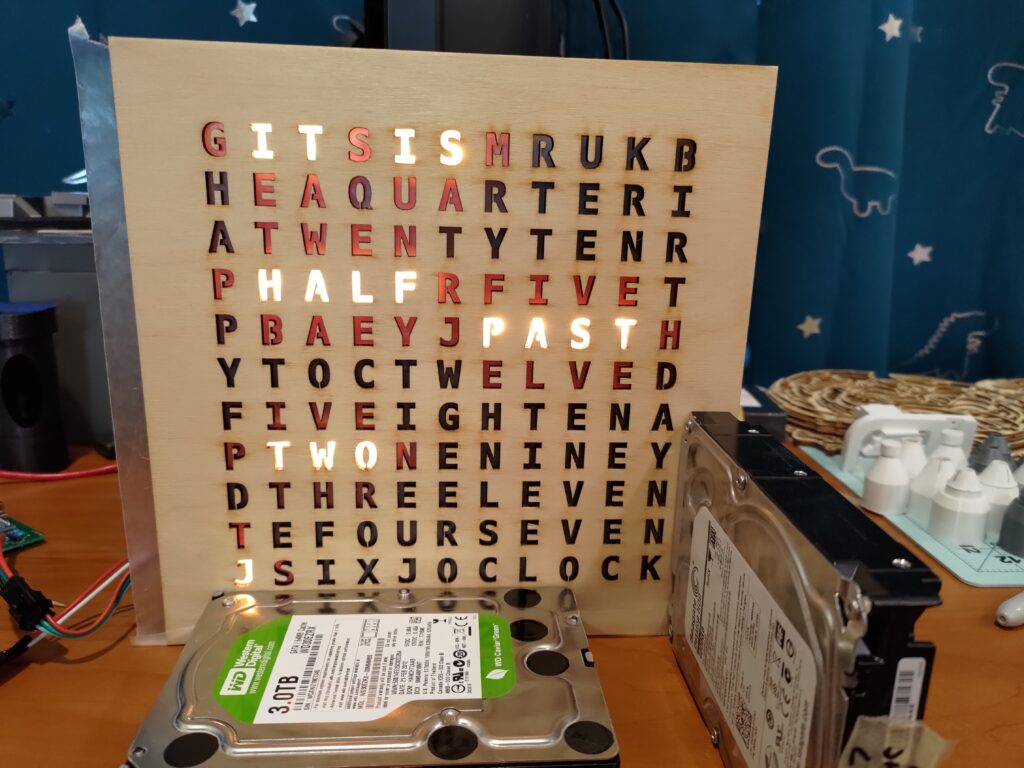
I hooked the unit up to a spare WLED controller that I keep around and was able to drive all 122 LEDs in the strip to various colors without any problems. This was my test before integrating anything else into it to make sure it was all working.
Nothing goes right, after a miss on my planning, my LED strips don’t turn the right direction to match the design. This isn’t too big a deal, it can be fixed in software which will be far easier than fixing it in the hardware right now. Once I finished mounting the LED strip, I hooked it up to a spare WLED controller that I had laying around and used that to test and make sure everything was working correctly.
Software
The software itself needed a bit of TLC. It has missing parenthesis on if statements, wrong/typo variables, and generally had no chance of compiling without a decent amount of work, let alone making it work well. I also wanted to add some capabilities to it, alongside resetting the LEDs to my clocks layout. The code and design however, had other ideas for me. I thought it had started out well, but ended up quite quickly running into odd bugs. I would have letters light up when they shouldn’t, letters that should light up that aren’t. All inconsistently as well, and since I had already had the urge to run this on an ESP rather than the Arduino, this was just more reason to do so.
Swapping to an ESP Controller
After all the problems with words not lighting up correctly or lighting up when they shouldn’t, I knew for sure to go with the other controller and rewrite the firmware. I also didn’t like setting the time with the Bluetooth terminal app, although an alternative was to use an ESP to send the time updates over BLE. Since there were a few problems all at the same time, I decided to go with the alternative controller and firmware over making a BLE time updater ESP32.
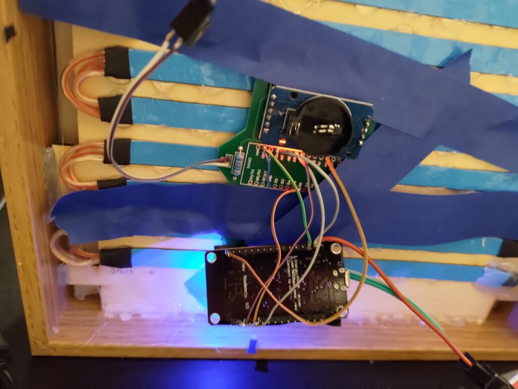
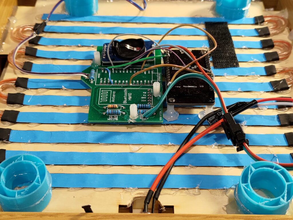
I started my swap to the ESP32 controller by assembling a second PCB with everything but the bluetooth adapter soldered in place. I then hand wired the ESP to the correct pins on the circuit board so that it could read the light sensor, drive the LEDs, and possibly in the future, use the RTC.
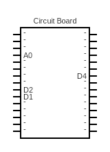
- D4: GPIO 2: LED strip
- A0: GPIO 17: Light Sensor
- D2: GPIO 4: RTC
- D1: GPIO 5: RTC
After swapping to an ESP 8266, I needed to start working on the software again. I did find a repo where someone made a word clock in the same way as I was working on with ESPHome and an addressable LED strip, so I wasn’t starting from scratch. But their code used a deprecated library that no longer works with recent versions of the Arduino frameworks. Luckily the change isn’t too hard to a new library, assuming the library works.
Sadly, that’s exactly what happened. I first tried to use the neopixelbus library, however this ended up being a bad decision. I spent a few hours trying to figure out why nothing was working with this library, even basic demo code that they had provided. My only guess is that the library has a bug and doesn’t support custom pin selection for the output pin. Luckily, I next found the Adafruit Neopixel library, which does work amazingly well.
Over the course of the upgrade, I split out the library calls into wrapper functions in case I wanted to swap libraries again, it would only require changes in those functions instead of changes spread through the entire codebase.
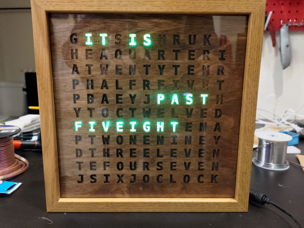
Eventually I did get it working and have everything now running nicely in home assistant via esphome and without any of the bugs that the old Arduino code had.
Final Hardware Assembly
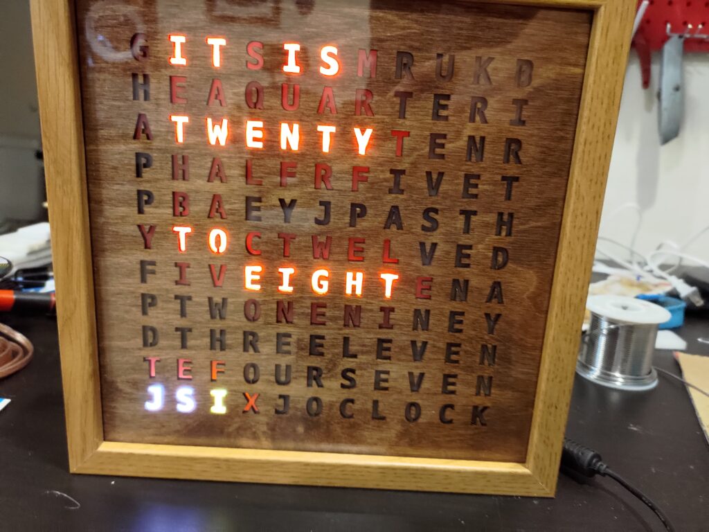
Now with the controller working, and the software running without any odd letters lighting up, I have it all working again. I had to start assembling everything into my chosen picture frame. I hot glued everything in, starting with the letters, the wax paper diffuser, the grid, the LED plate. Next up the circuit board was mounted to the LED plate with velcro, and the ESP was given standoffs, and mounted nearby as well. I used some dead 3d prints as standoffs for the backplate of the clock, giving it the bit of extra space needed for the clips on the back to hold the plate in and keep it all together.
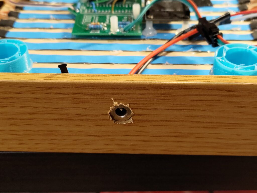
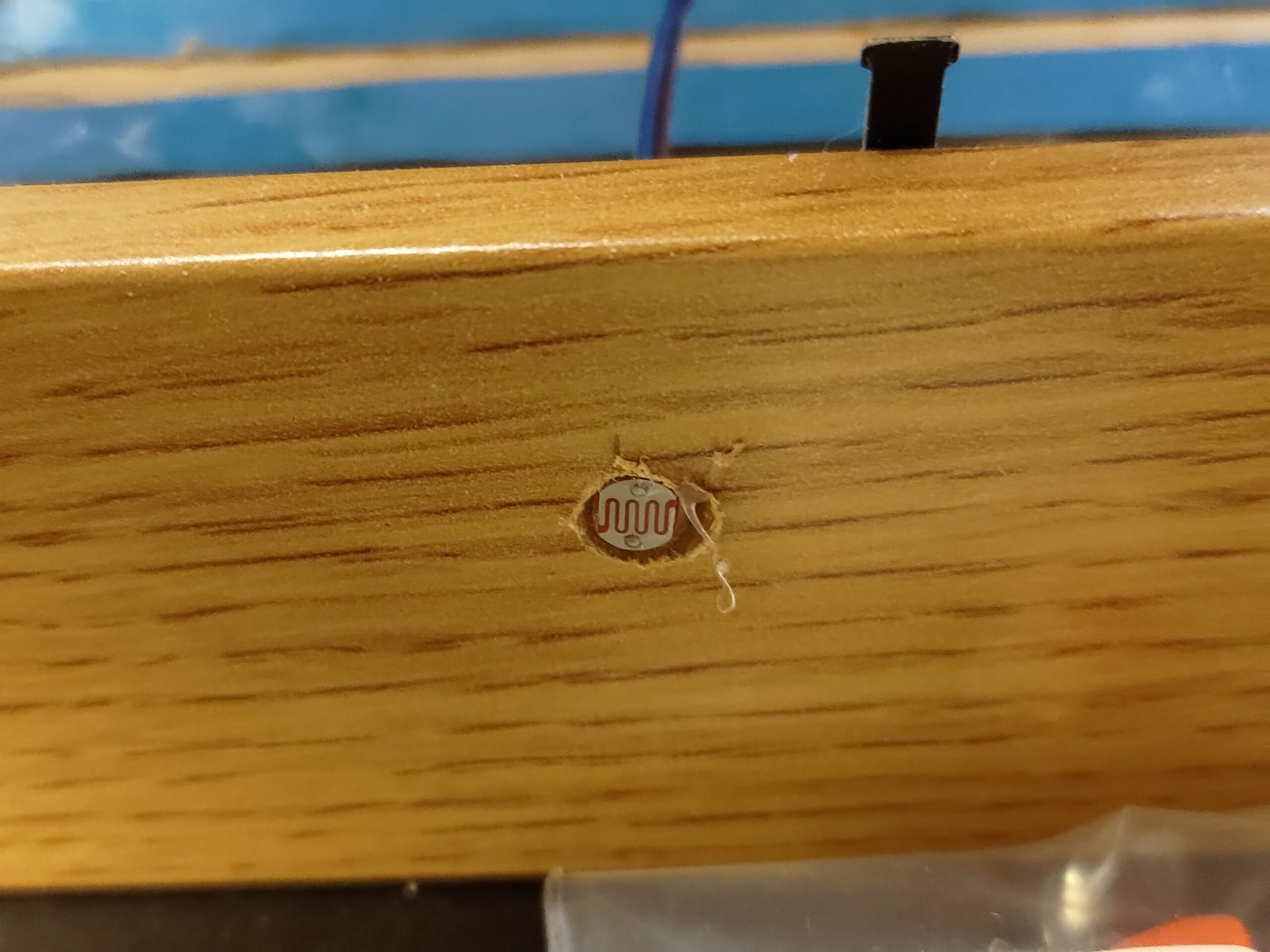
I also drilled holes for power and the light sensor. I mounted both of those with hot glue and connectors, in case I need to work on the electronics, it would only be a few connectors and some hot glue to remove it completely from the clock. Finally I mounted the backplate, and hot glued it all into place, liberally hot glued into place.
Conclusion
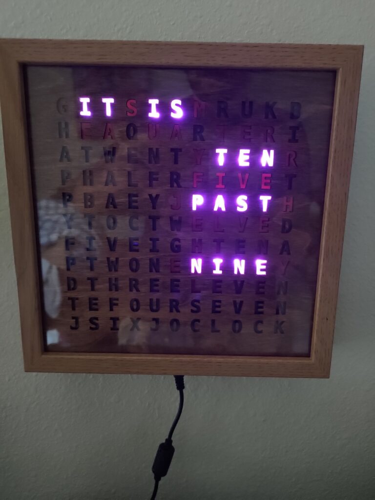
Once I got it all working on the ESP32, I was quite happy with it. The new libraries didn’t show the bugs I was seeing before, and I didn’t need any code for daylights savings time since the time was all synced from the server. It does however have the drawback that you do need the home assistant server for the clock to work. I may be able to fix that with the RTC in a later software upgrade, but those are far simpler now that the clock can be upgraded over the air.