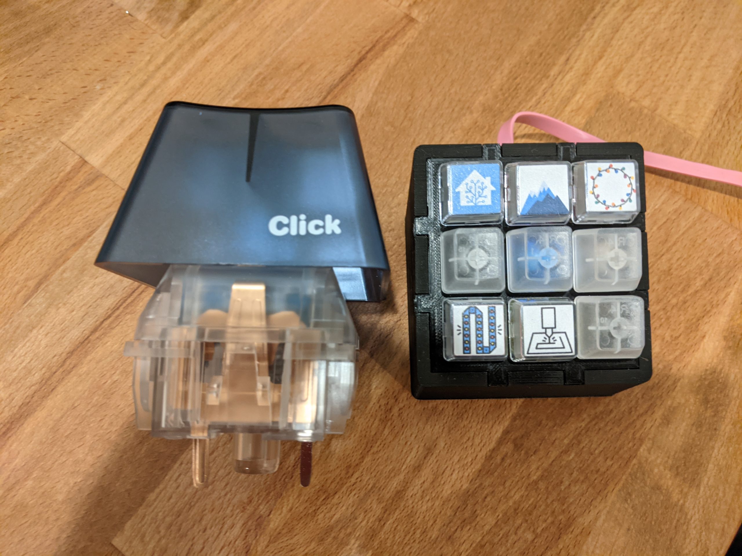
After putting together the EspDeck 9 key pad, and talking to the wife of other places we could make things better, the bedroom fan and lights came up. I mentioned that we could use smart switches for them and make a small 2 key control for our night stands, which she was super excited about, and then I showed her the NovelKeys big switches and it was sold, we were going to have some hilarious macro pads to control our bedroom lights.
Hardware:
- 2 x Novelkeys big switch
- ESP8266
- Wire
- 3d Printing Filament
- 2 x LEDs
- 2 x 300 ohm Resistors
- 3 x 3 Pin JST Connectors (optional)
- 4 x Rubber Feet
Functionality:
- Button 1:
- Single Click: If one light is on, turn them both off
- Single Click: If both lights are off, turn them both on
- Button 2:
- Single Click: Toggle Fan
- LED Backlighting
- At Sunset: Turn on LED Backlights
- At Sunrise + 1 hour: Turn off LED Backlights
- Future capability:
- Button 1: Double click for WLED toggle
- Button 2: Double click for fan speed
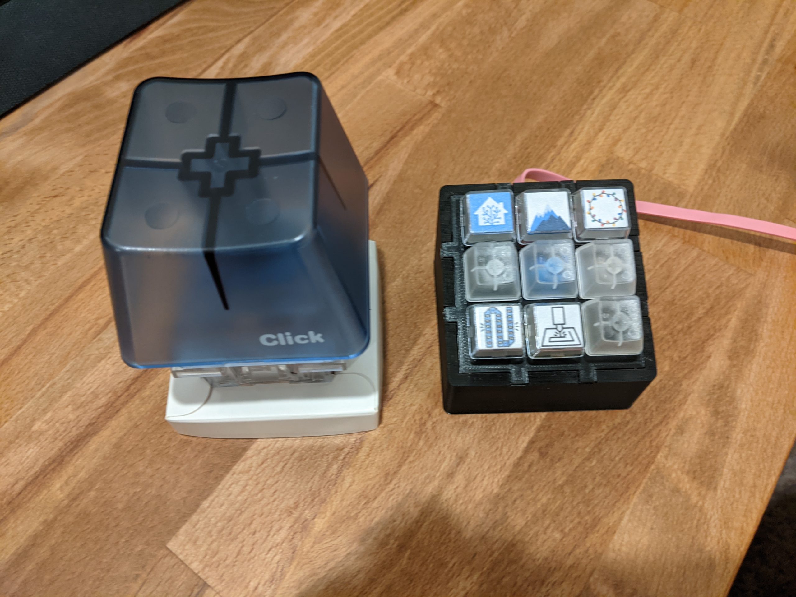
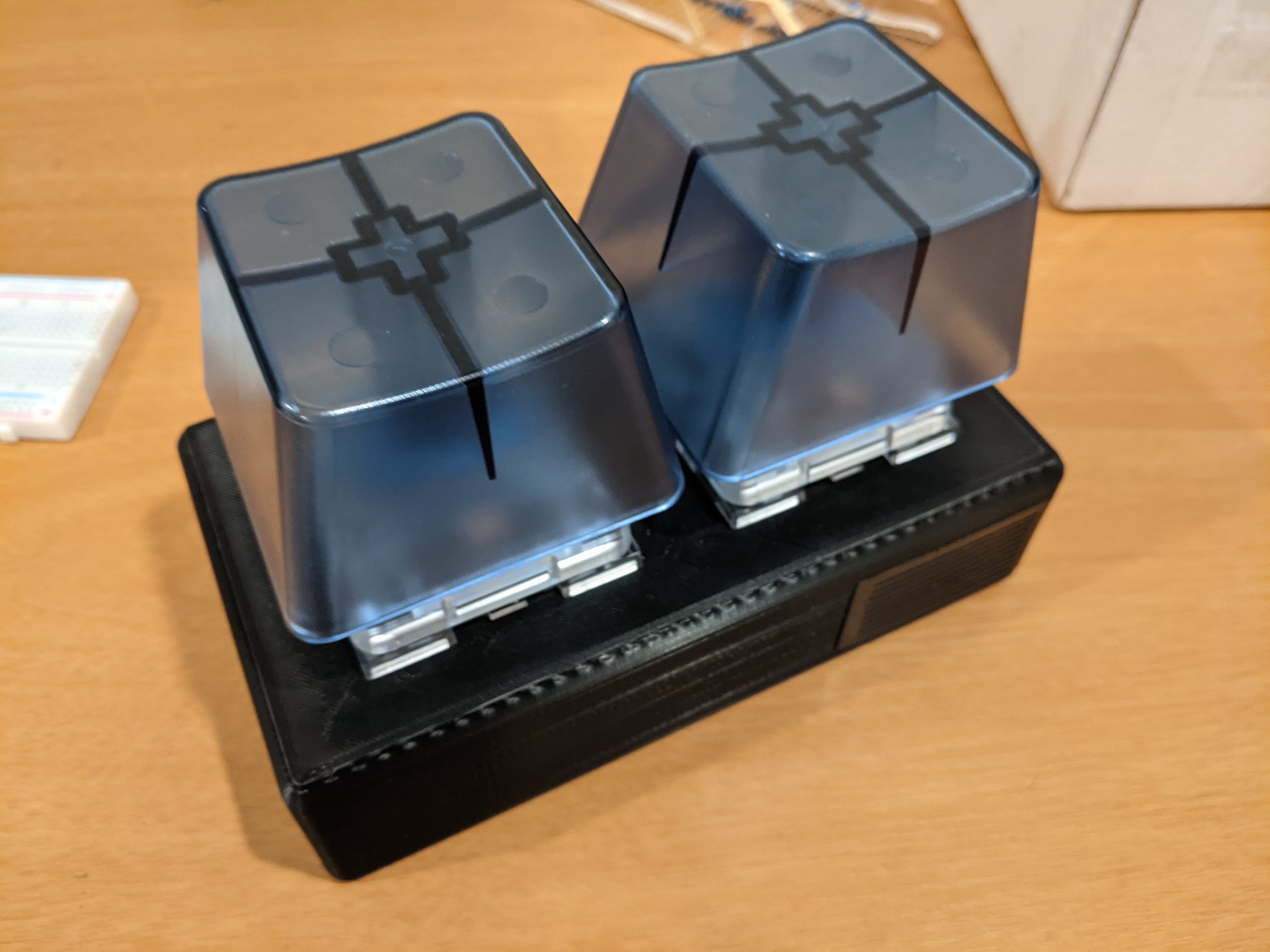
BIG Switch
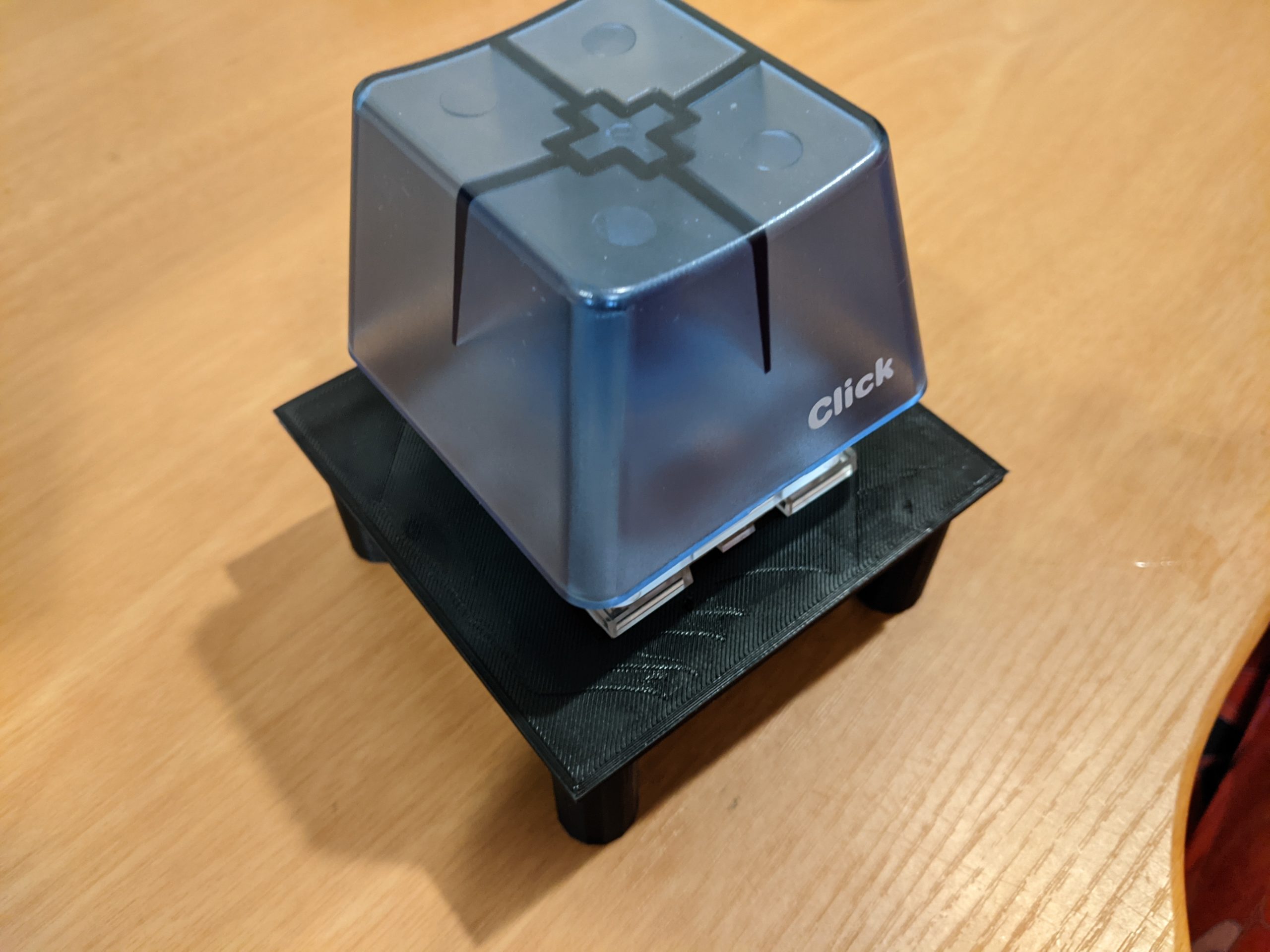
After seeing the switches, I realized how big the case was going to need to be, probably 2.5 times the size of the original EspDeck case. This was going to be a bit daunting, also I thought I would need some type of weight in the bottom to keep them from tipping over. After getting the first unit fully assembled, I realized that wouldn’t be necessary at all, they are very stable without any extra weight.
Case
I started by designing a stand for the switches. I figured the best way to start would be to figure out how best to hold them, how much space is needed for the stem and pins, and how tightly I can hold the switches WITHOUT hot glue. I also figured I’d end up with one of these big switches at some point on my desk, so having a little stand for it would be nice.
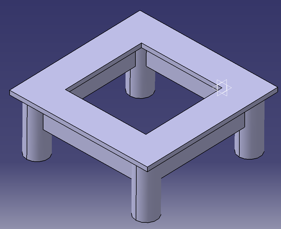
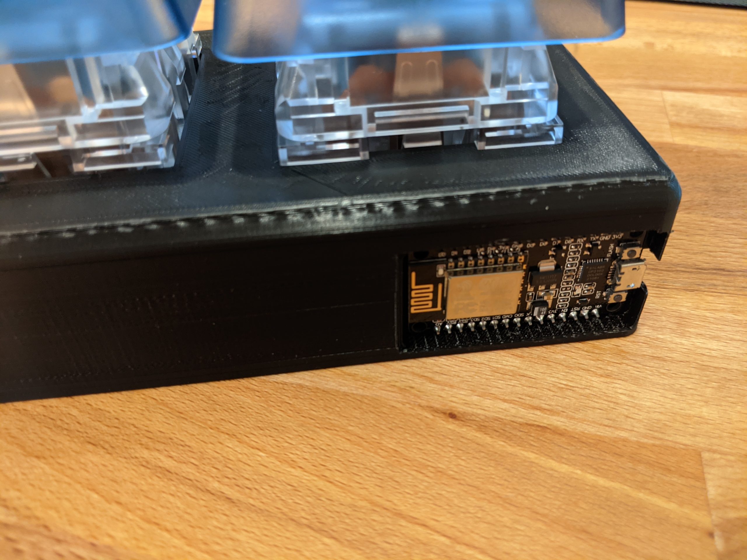
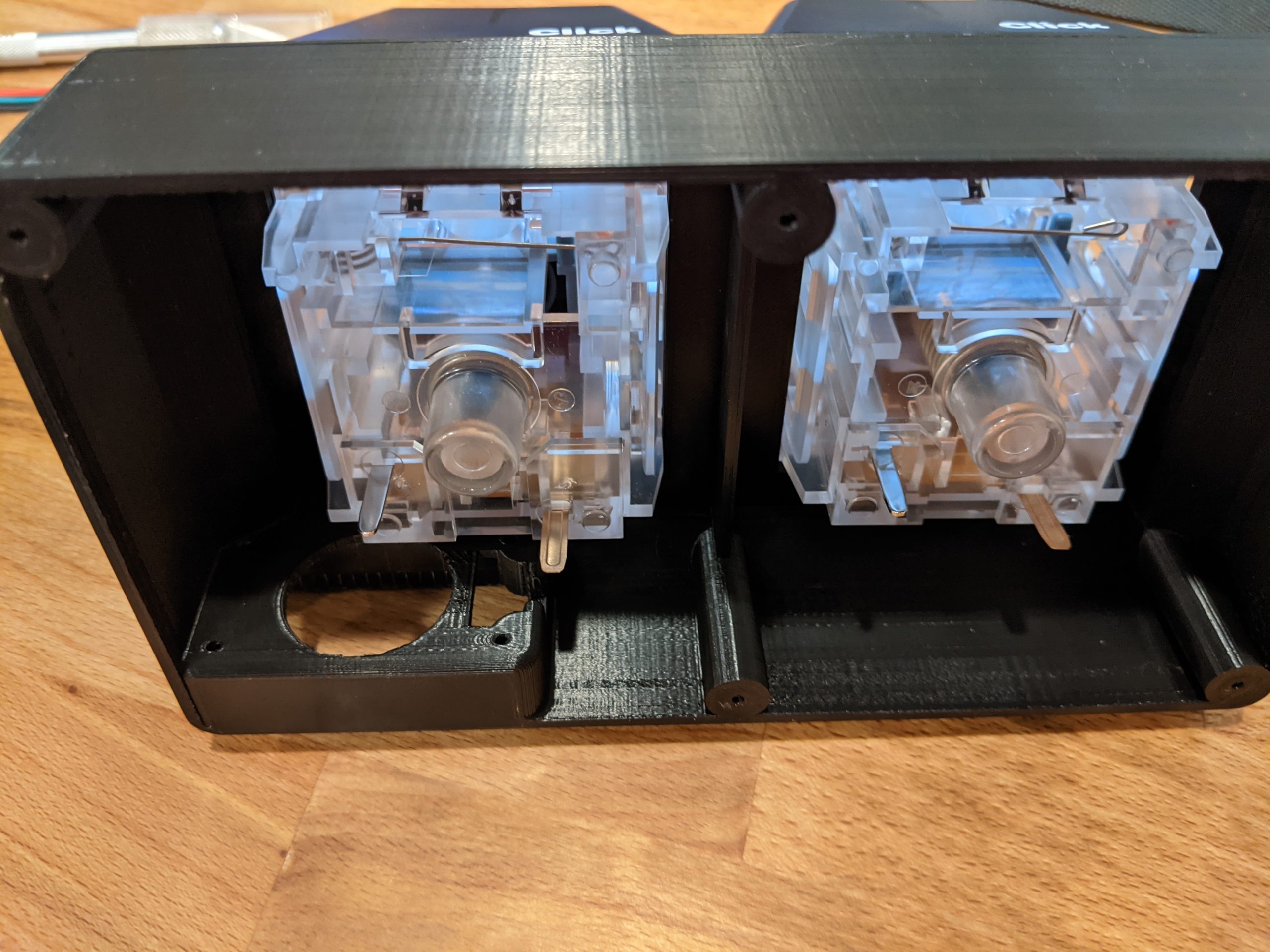
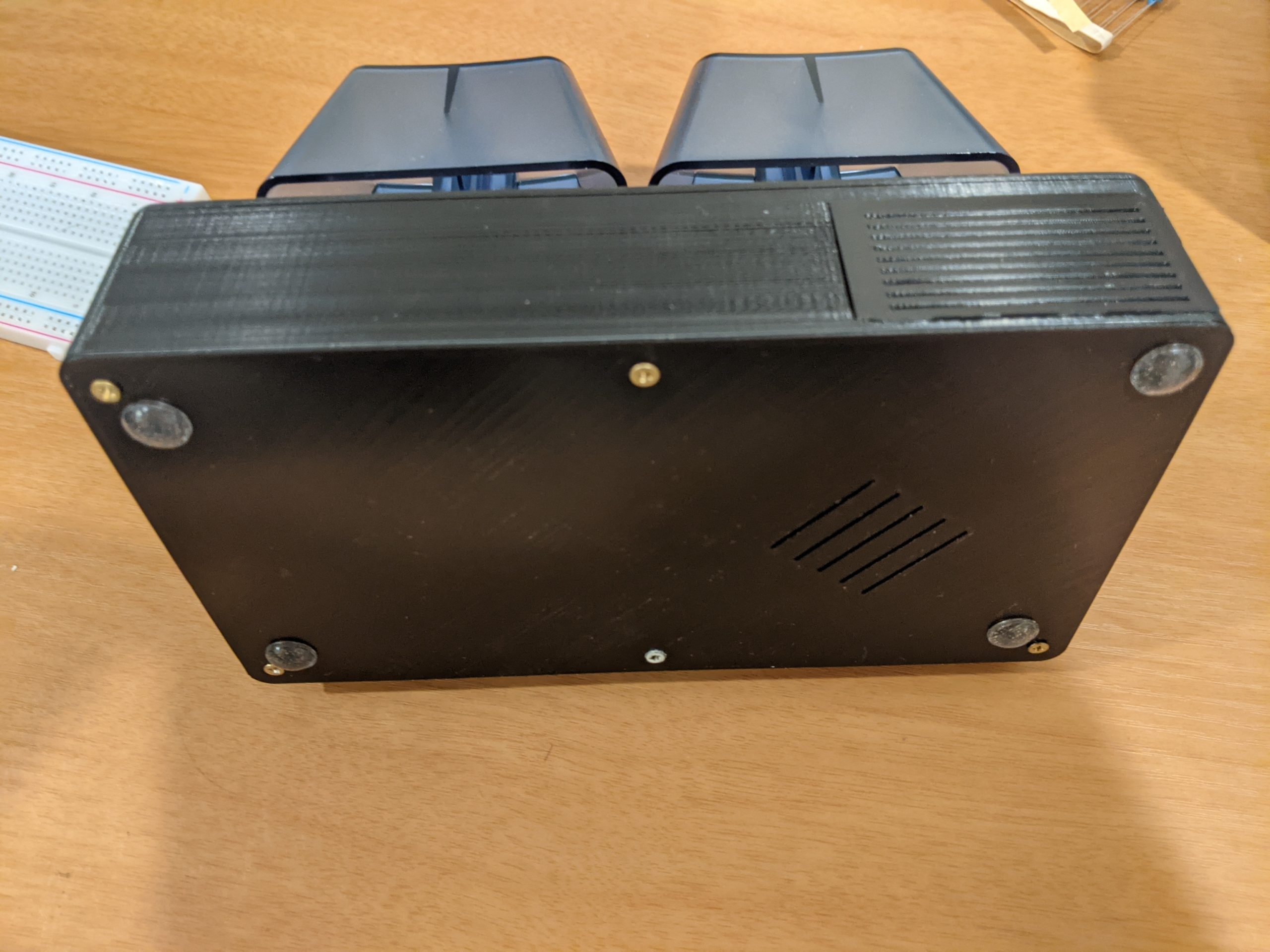
With the switches working in the stand, time to model the final case. I used the stand to figure out where best to situate the ESP8266 and then started modeling the base unit of the assembly. I found that mounting the ESP8266 vertically would fit the best next to the big switches. I modeled the enclosure as best as I could to avoid any problems with wiring, or plugging in the USB cable (cough gen1 EspDeck cough). It is 3 pieces total, the enclosure, bottom plate, and side plate. The side plate covers the ESP and allows direct access to it (press fit) while the bottom plate is screwed on with countersunk screws (and feet to keep it from scratching anything).
A test fit of the switches into the enclosure was successful. There is plenty of room for wiring the switches, LEDs, and the JST connectors.
Wiring & Assembly
We’re starting out with the limitations on using the ESP GPIO pins to drive devices. These pins have a max output current of 12 milliamps (and output 3.3v). With this in mind, we can calculate how big the resistors need to be to prevent damage to the ESP circuit.
V=IR
Voltage = Current * Resistance
3.3v = 0.012 amps * X ohms
X = 275
We’ll be using 300 ohm resistors (maybe more to dim the backlighting). With this in mind, we can draw out the circuit diagram.
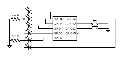
GPIO 12 and 13 were picked for the inputs as they can have the internal pull-up enabled (GPIO 15 and 16 would be bad choices for the inputs). The other GPIOs picked for the LED outputs to avoid any odd boot pins for the ESP device. Now we can start prototyping the LEDs (since I haven’t done anything like this before, lots of demoing before soldering).
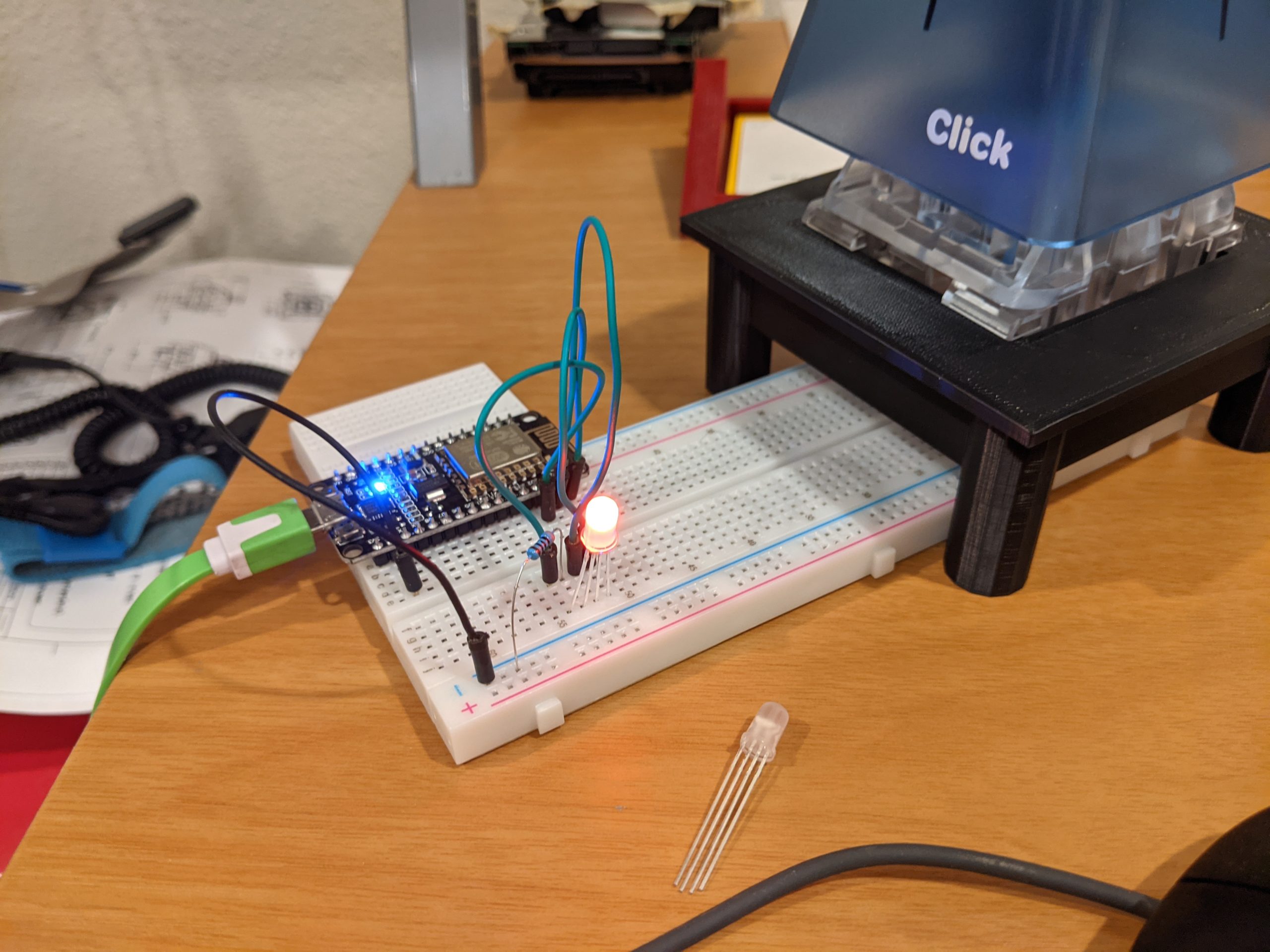
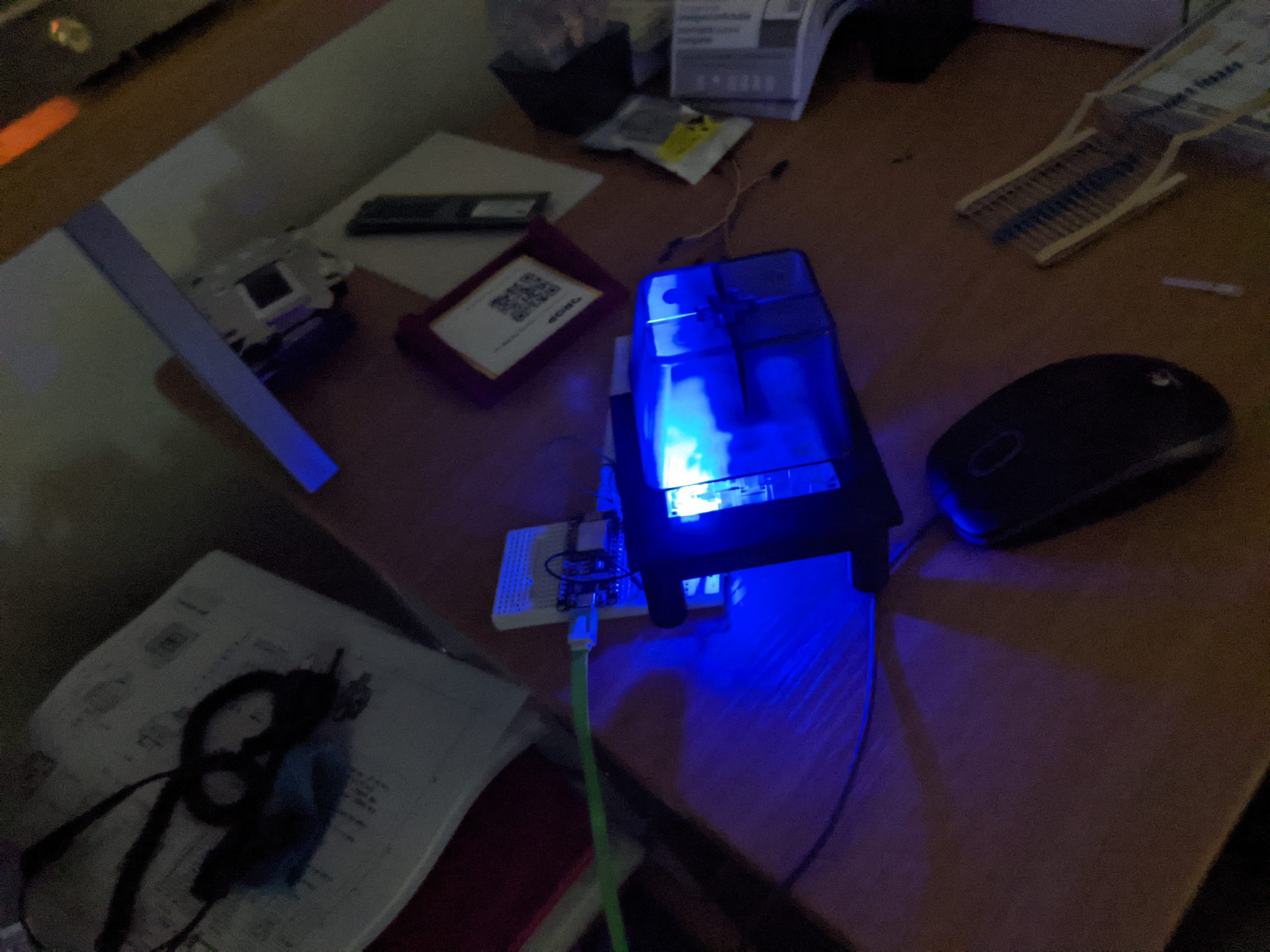
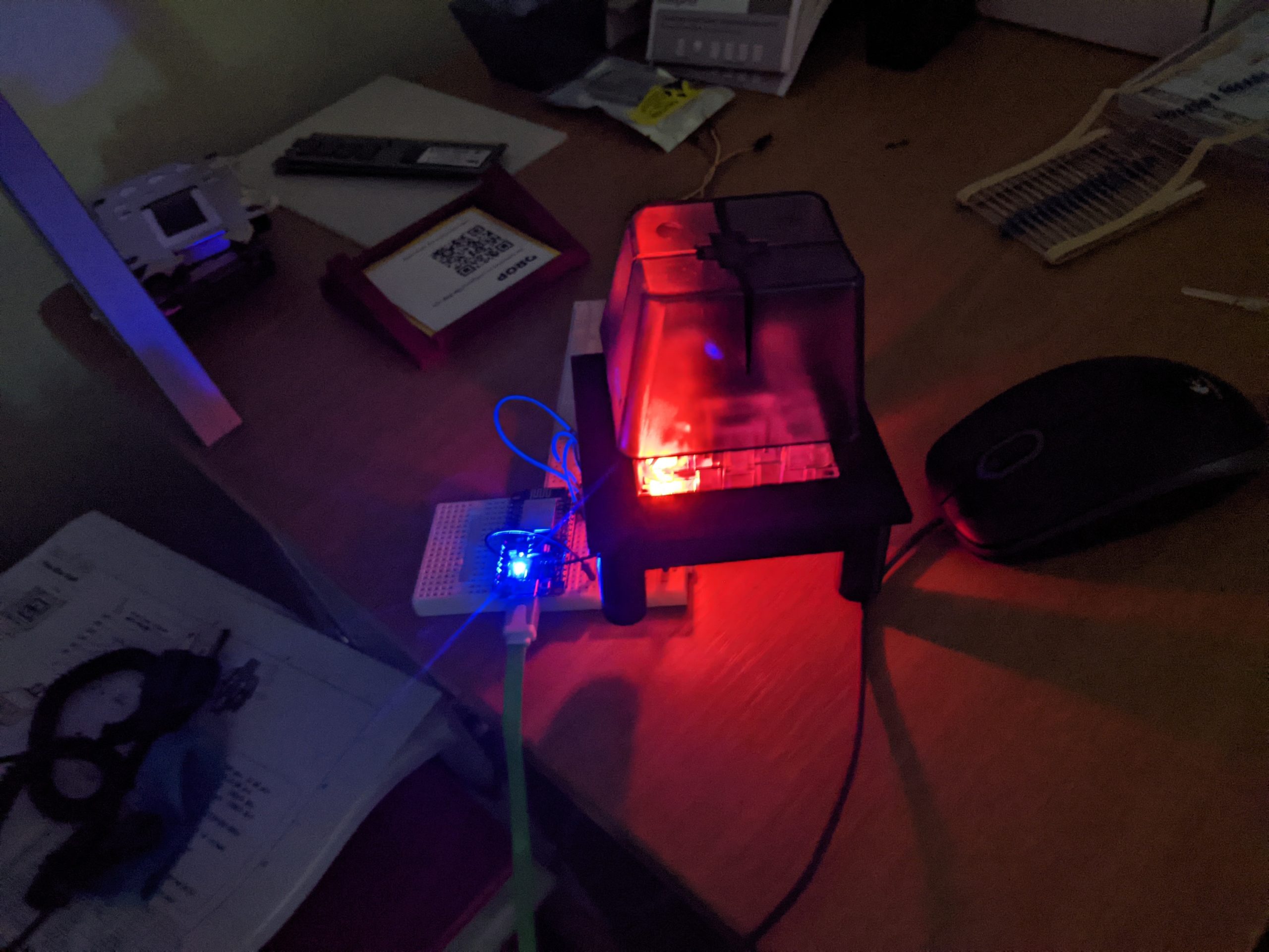
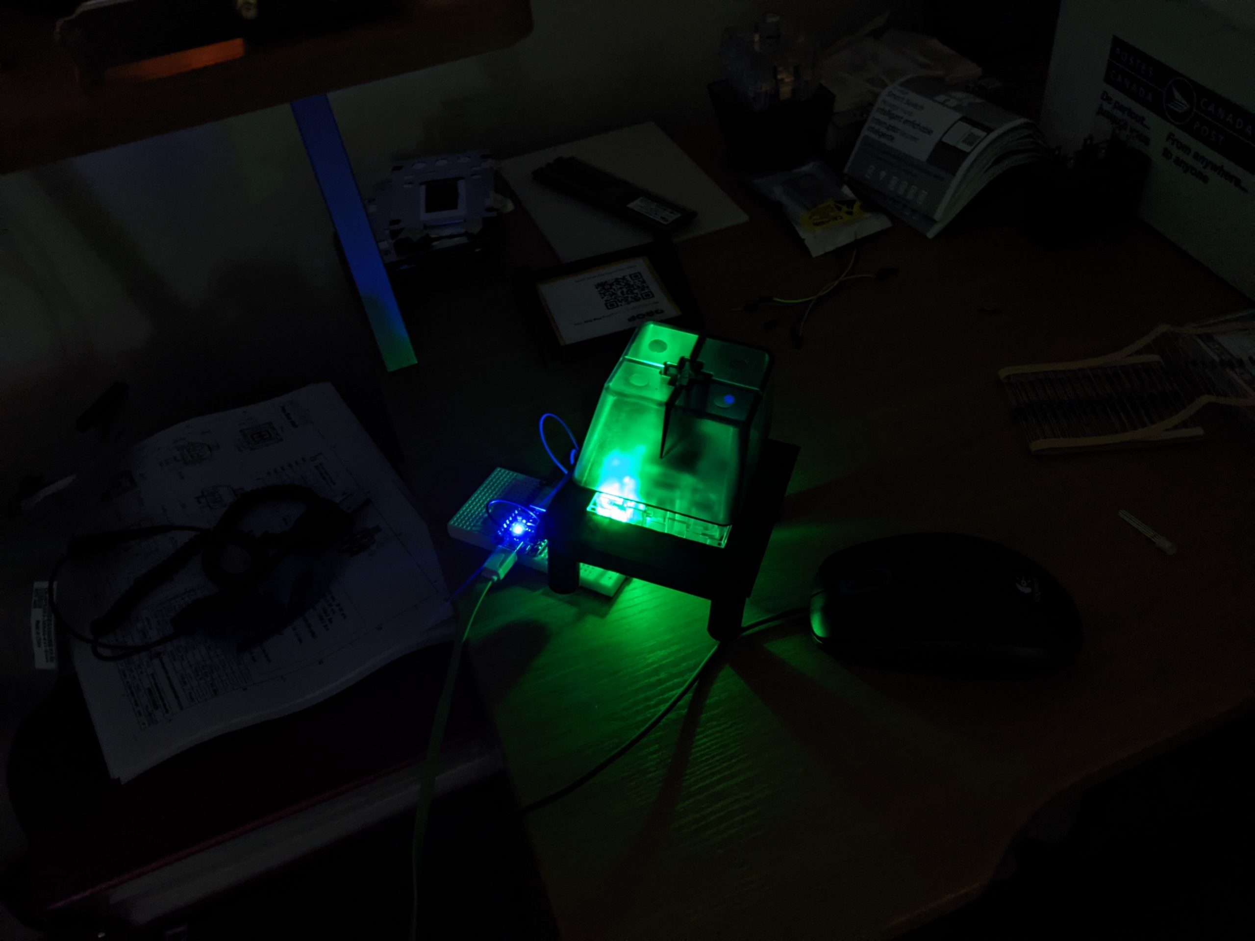
I also wanted to make sure the LEDs would have the intended effect for backlighting the switches at night. I found that it worked flawlessly and was plenty bright (maybe too bright for the night stand though).
I soldered on 3 pin JST connectors to each LED, and one more for the two switches and a ground wire. I decided to do this so I could remove the ESP8266 by simply unplugging everything and pulling the wiring out of a hole betwen the ESP holder in the pad and the main opening in the pad.
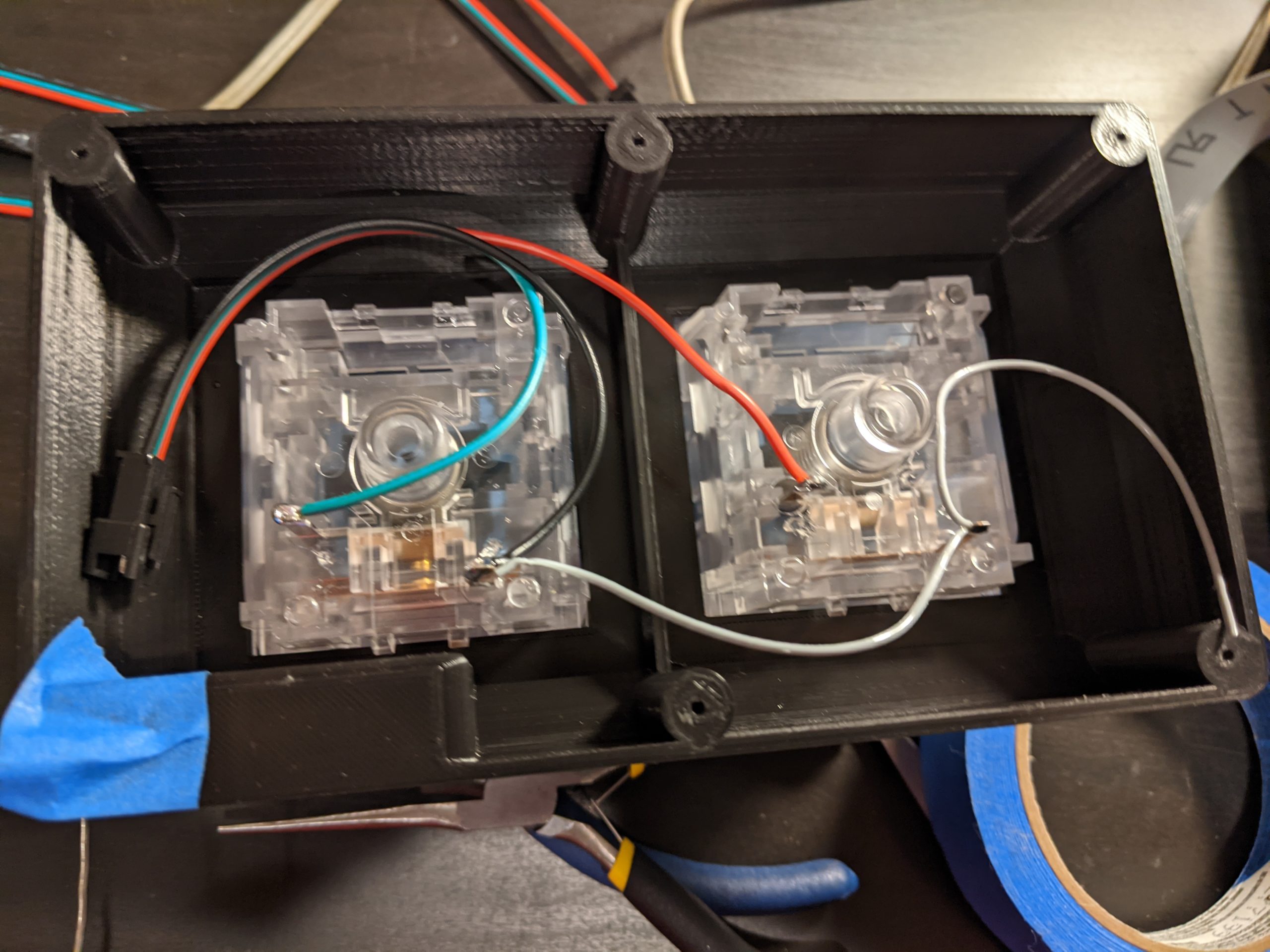
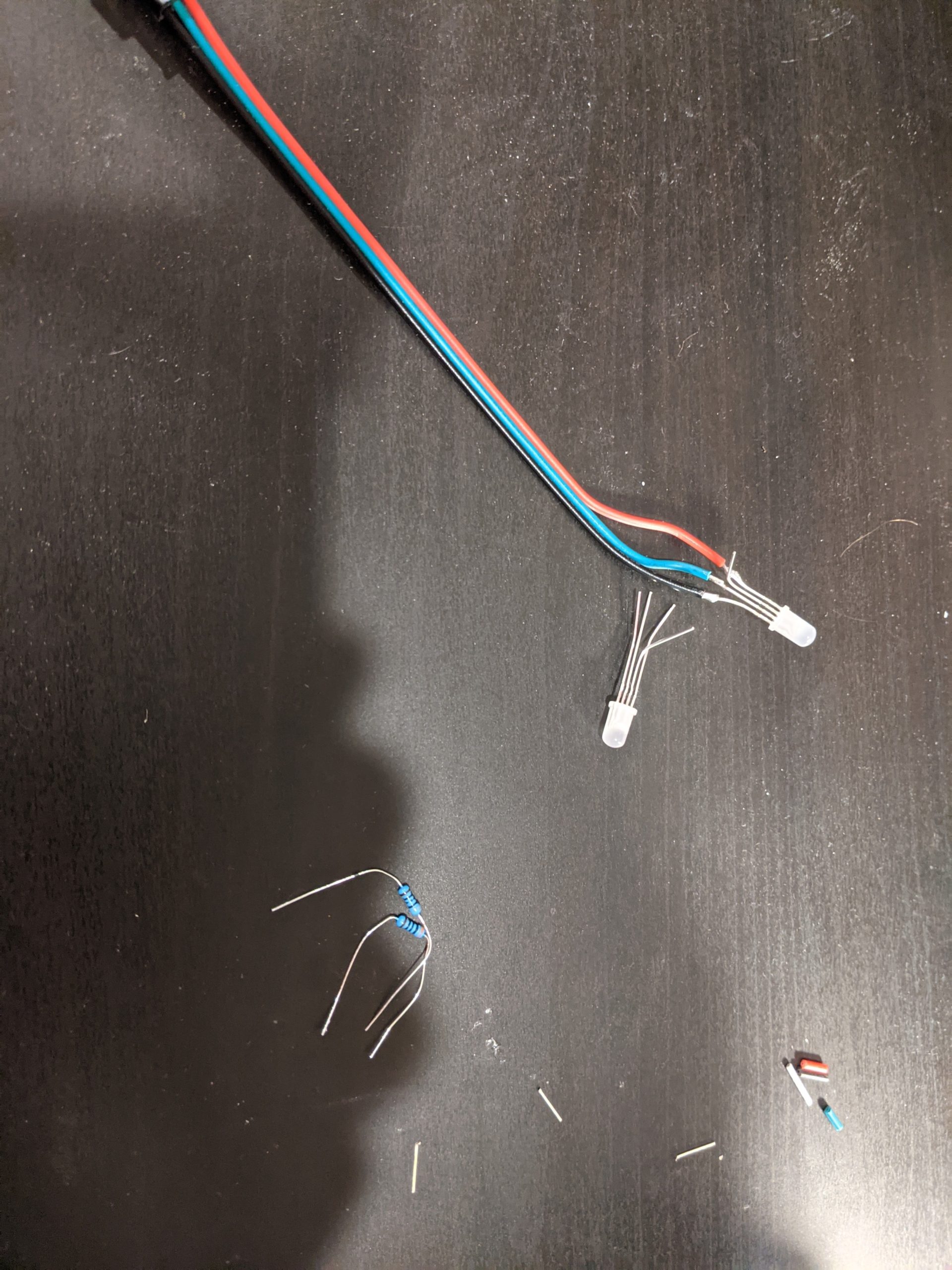
I soldered the resistors onto each LED and then used the common ground that goes back to the ESP on the switch connector.
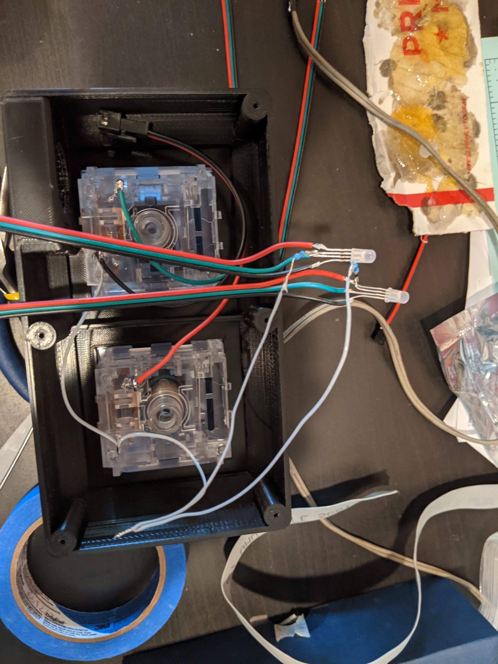
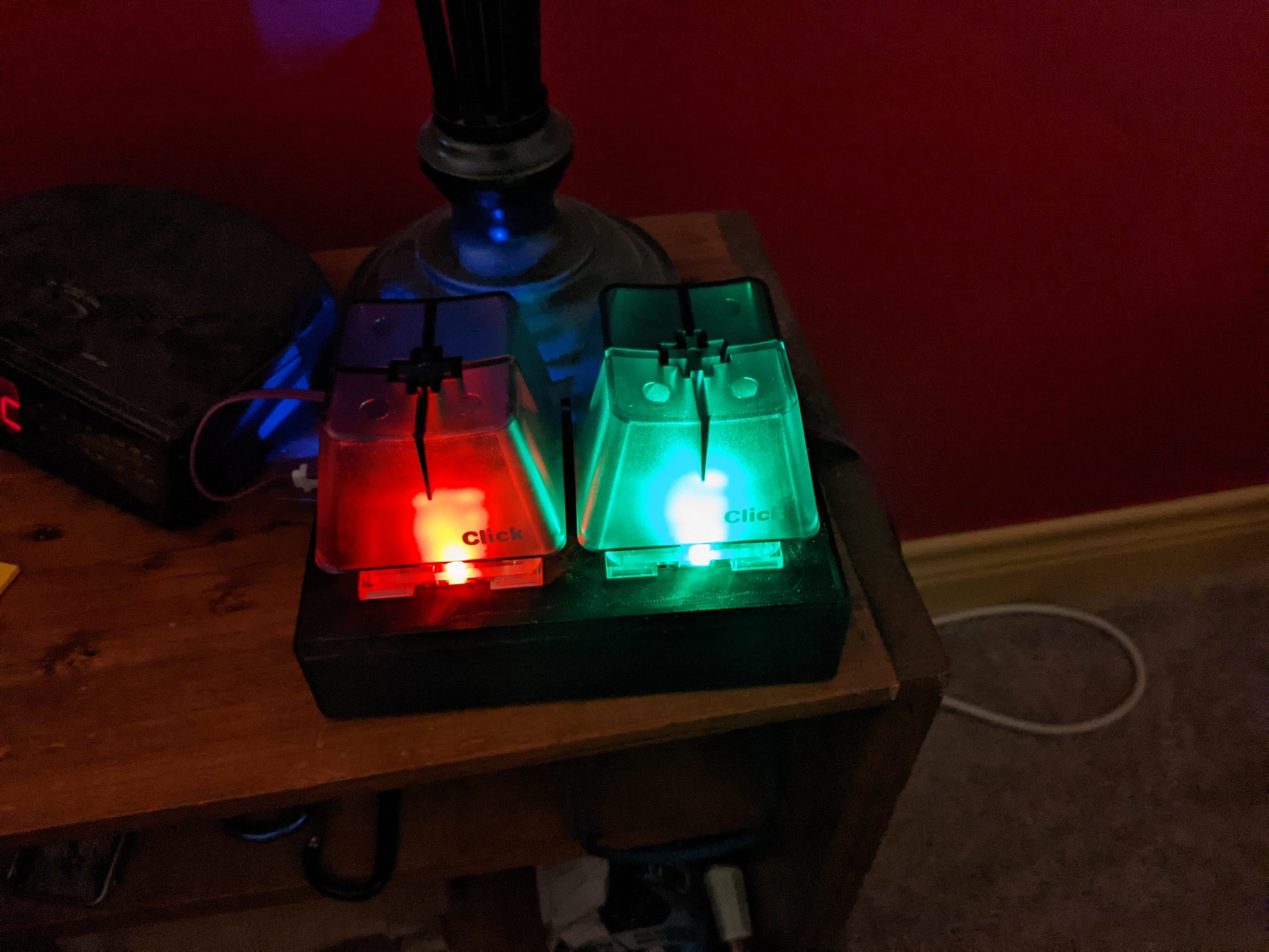
Everything then was connected and tested before being fully assembled. The LEDs are hot glued into place (okay so I couldn’t avoid using hotglue completely, but at least its minimized).
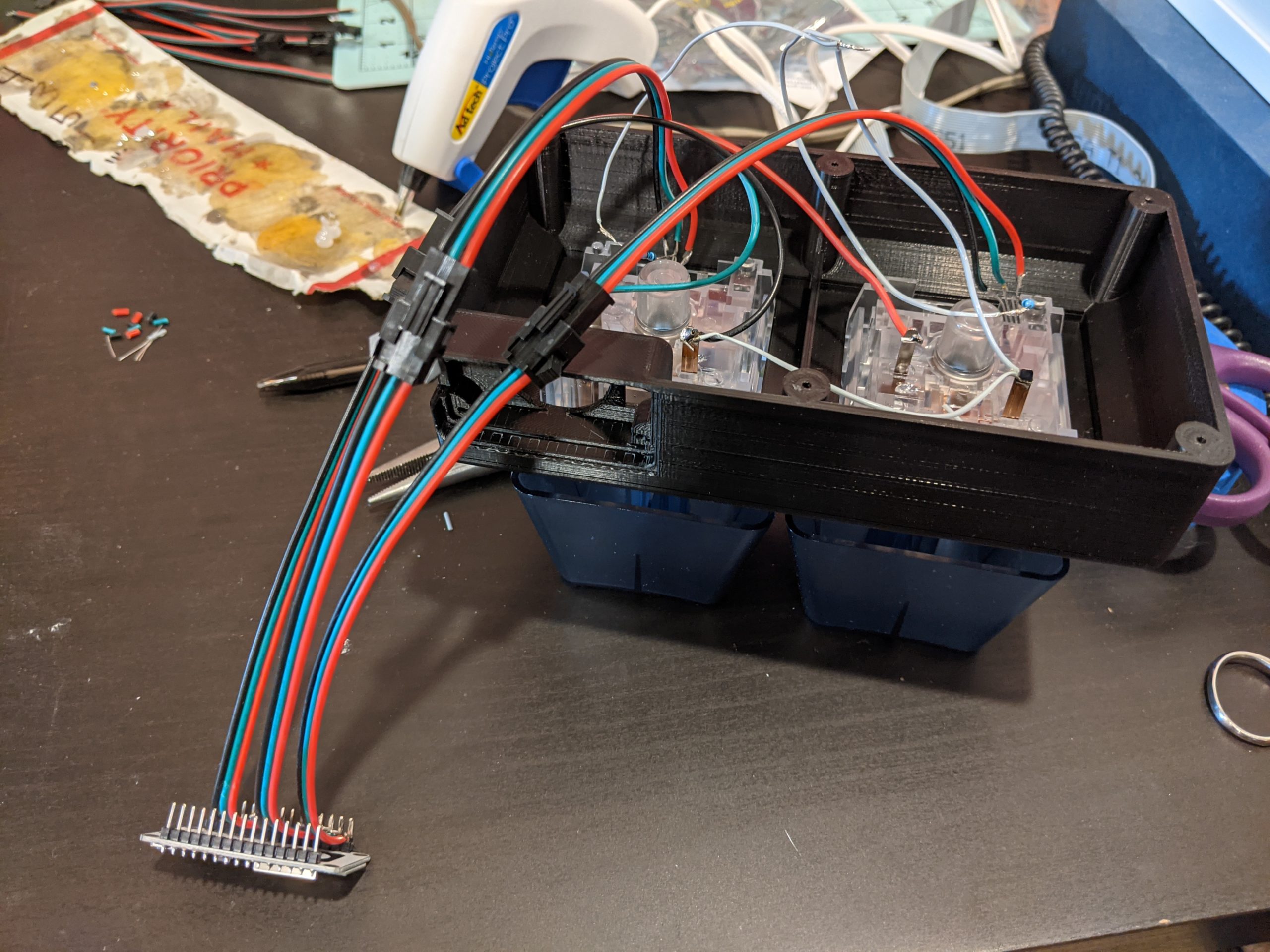
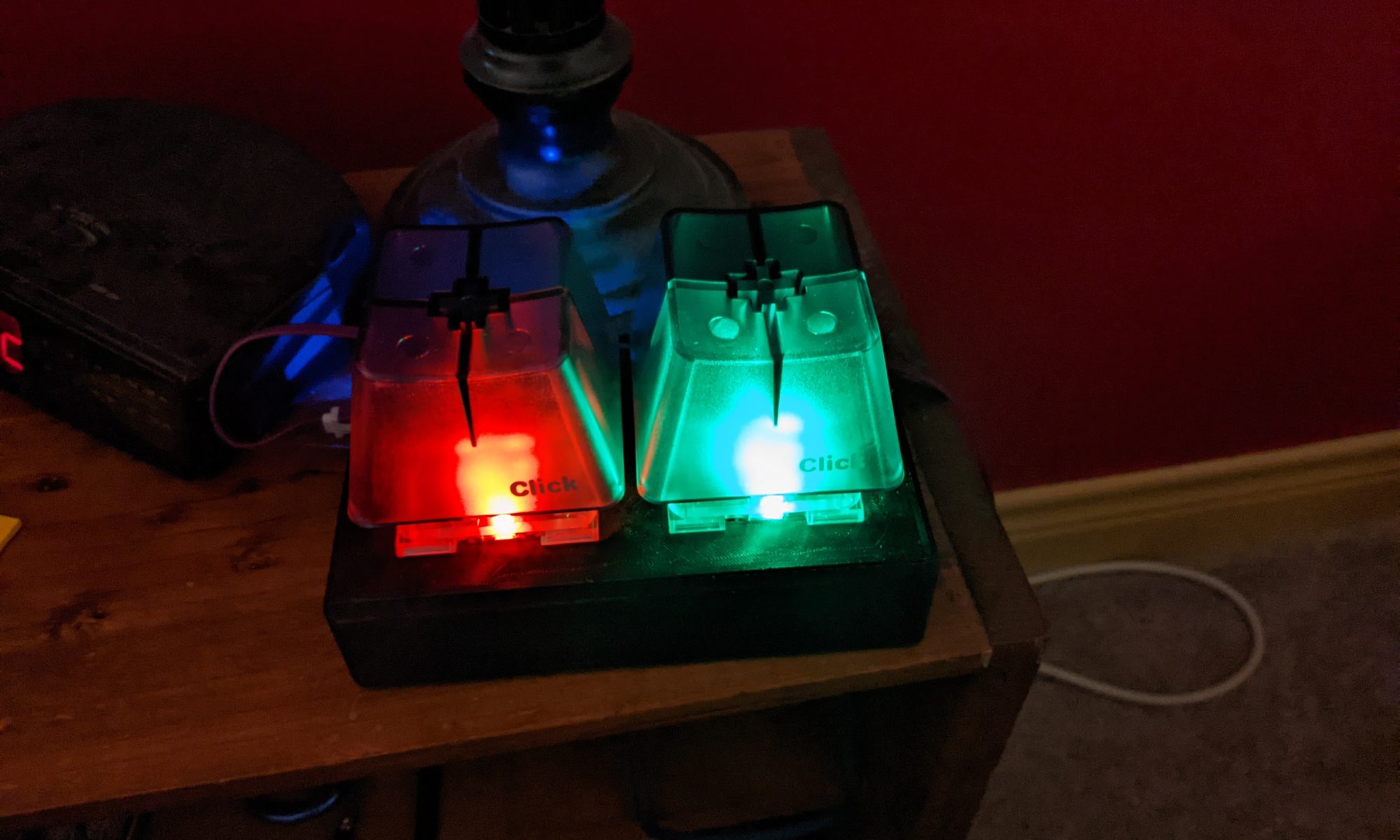
And the final assembly completed. We have the bottom plate screwed on, feet stuck on, and side plate pressed into place. The USB cord reaches the plug fine, so no problems there, and everything is working.
Conclusion
The keypad works great, its big enough that its hard to miss when groggily trying to turn on the lights when a dog starts gagging, or when trying to turn on the fan when the room gets too hot at night. With Z-Wave switches on the wall for everything, there’s nearly no lag when clicking to when the action takes place.